Another viewpoint
I got exactly the same results when running Mooly's LTSpice file. It is odd that using double C-L-C filter blocks does not filter the ripple better than the sim is showing.
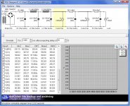
Here's another view from PSUD. It does not allow arbitrary placement of component values, so this is the closest I could get. The PSUD simulation is running at 50Hz mains. Results look really good.
Note the voltages on the secondary of the power transformer are the same as the LTSpice simulation, it's just that PSUD specifies AC voltages in RMS values.
The voltages and ripple values interest are:
V(C3): 343V, ripple: 625 microvolts (p-p)
V(C4): 304V, ripple: 11 microvolts (p-p)
V(C5): 205V, ripple: 77 nanovolts (p-p)
Ripple seems to be extremely low from the PSUD point of view, which should produce a whisper quiet headphone amp, as I would expect when using double CLC filter blocks.
I got exactly the same results when running Mooly's LTSpice file. It is odd that using double C-L-C filter blocks does not filter the ripple better than the sim is showing.
Here's another view from PSUD. It does not allow arbitrary placement of component values, so this is the closest I could get. The PSUD simulation is running at 50Hz mains. Results look really good.
Note the voltages on the secondary of the power transformer are the same as the LTSpice simulation, it's just that PSUD specifies AC voltages in RMS values.
The voltages and ripple values interest are:
V(C3): 343V, ripple: 625 microvolts (p-p)
V(C4): 304V, ripple: 11 microvolts (p-p)
V(C5): 205V, ripple: 77 nanovolts (p-p)
Ripple seems to be extremely low from the PSUD point of view, which should produce a whisper quiet headphone amp, as I would expect when using double CLC filter blocks.
Attachments
It's probably worth putting in some realistic figures for resistance in the inductors, and source voltage impedance, I would suspect. I can imagine that with the assumption of "ideal" components there could be unrealistically big transients which, together with accuracy limitations in the the algorithms, could give Spice some problems in the simulations.
Another thing I just tried was simply putting .01uF snubber capacitors across each of the four diodes, and that greatly reduced the fluctuations at the various voltage points down the line.
Chris
Another thing I just tried was simply putting .01uF snubber capacitors across each of the four diodes, and that greatly reduced the fluctuations at the various voltage points down the line.
Chris
- Status
- This old topic is closed. If you want to reopen this topic, contact a moderator using the "Report Post" button.