I'm seriously investigating this design
http://www.users.globalnet.co.uk/~valveamp/images/SE108IT2.GIF
I'm am looking for someone who has built it. I will still make changes to the design but that is not important at this stage. I am particularly interested to find a layout for the iron that worked well with minimal hum. The person supplying my iron has made mention that laying the iron out is critical to avoiding induced hum - particularly as this design uses 8 TF, Chokes per monoblock.
Can anyone help me or am I back to experimenting at construction time?
Thanks and Regards
Ralf
Konnichiwa,
Well, I cannot fail to gleefully that all these supposed experts with their "extensive experience" are quiet wehn it comes to very simple, practical questions. I would have answered earlier but I was pushed for time and wanted to give all those with their superior experience an chance before ingnorant old me gives advise.
Anyway, first it is important to understand why the layput of the iron is critical. Any transformer will have a (variable) magnetic field around it when (alternating) current passes through it. Equally, if a transformer is placed inside a (variable) magnetic field a current will be induced in the windings. The exact shape and the direction of the strongest field output and or pickup depends heavily on the transformers construction.
Normal E/I Transformers have the strongest field/pickup along the winding axis (along the length of the "I" bar that passes through the winding former). Torroidal transformers will have the field along the axis where the bolt passes through the transformer and so on. Often it is best to simply apply some AC to a transformers whose fielddistribution is unknown and use a headphone with headphone Amp (high gain) and snooper coil to find on which axis's the field is strongest, especially with encased transformers.
The layout should be done so that the supply transformers / chokes with the strongest fields (main mains transformer and Input choke) are one one end of the chassis, well away from any low level connections and well away from the output and interstage transformer. The next items on the chassis would be power supply rectifiers, chokes and/or transformers with lower (AC) current load etc., power supply capacitors etc with finally the signal transformers.
The signal transformers should also be rotated/oriented such that their main axis of magnetic field suceptibility is 90 degrees offset from that of all mains transformers and chokes. Ideally one uses a dual 90 degrees rotation away by for exampe using "drop through" type mains transformers and supply chokes and "shrouded standing" type interstage and output transformers or visa-versa. A good illustration of best practice when mounting Mains & Output Transformers is shown in this amplifier:

Even better would be to seperate the entire powersupply EXCLUDING the final Supply capacitors into a remote chassis, more or less the way it is done by Borderpatrol in the UK who build what might be considered the "commercial" version of the SJS design.
Here the amplifier Chassis:
And the inside of a powersupply (they use 2pcs - one per channel in their top of the range Amp):
More info from their website and in the various reviews posted there:
http://www.borderpatrol.co.uk/
Finally, if you insist on fitting all iron onto one chassis you might have a look aat how I did it when I chassis and some of the Transformers of the DIY HiFisupply "Billie" amplifier to my own design (which is very similar to SJS).
First a Photo showing the original positioning of Mains Transformer, Output and first Powersupply choke. Note orientation of these transformers, the Output is rotated so that it's main magnetic axis points int a direction 90 degrees opposed to that of the mains transformer and the choke is also oriented to minimise magnetic coupling:
I kept the original Transformers but added below the chassis two more Supply Chokes (one for HT and one for the heater supply) as well as two signal chokes, one operating as gridleak choke and the other as anode-load. I found this scheme (Grid & Anode Choke plus coupling cap) subjectively better than some seriously expensive IT's I tried:
Edit - link does not seem to work as inline, try this:
http://www.jogis-roehrenbude.de/Leserbriefe/TH-Loesch-Amp/LadyDay-chassislayout.jpg
Again, observe how the chokes are oriented. The ones mounted on the side of the chassis and rotated out of the magnetic axis of the maions transformer are the signal ones. The two under the chassis at a 45 degree angle are supply chokes, both are the chokes that handle comparably little AC currents and thus have a low magnetic field level.
BTW, the 4 big black cans are the Polypropylene Powersupply Capacitors, the two silver boxes contain homemade "block" capacitors using multiple lower value MKT Film capacitors paralleled and potted in wax to give high value, non polar cathode bypass capacitors. The very "chaotic" looking resistor array is a result from threedimensional layout aimed at making all current loops to have the minimal possible length and is INTENTIONAL btw.
For reference, the resulting amplifier has < 100uV output noise, this being purely magnetic coupled - a result of the chassis being magnetic steel (hint - use non-magnetic cahssis materials, it would have lowered my hum further), or in other words a Signal/Noise ration of -92db unweighetd, referred to 1Watt/16Ohm or -100db referred to nominal output (7 Watt @ 3% THD).
I hope the above helps.
Sayonara
DVDHack said:I'm seriously investigating this design
http://www.users.globalnet.co.uk/~valveamp/images/SE108IT2.GIF
I am particularly interested to find a layout for the iron that worked well with minimal hum. The person supplying my iron has made mention that laying the iron out is critical to avoiding induced hum - particularly as this design uses 8 TF, Chokes per monoblock.
Can anyone help me or am I back to experimenting at construction time?
Well, I cannot fail to gleefully that all these supposed experts with their "extensive experience" are quiet wehn it comes to very simple, practical questions. I would have answered earlier but I was pushed for time and wanted to give all those with their superior experience an chance before ingnorant old me gives advise.
Anyway, first it is important to understand why the layput of the iron is critical. Any transformer will have a (variable) magnetic field around it when (alternating) current passes through it. Equally, if a transformer is placed inside a (variable) magnetic field a current will be induced in the windings. The exact shape and the direction of the strongest field output and or pickup depends heavily on the transformers construction.
Normal E/I Transformers have the strongest field/pickup along the winding axis (along the length of the "I" bar that passes through the winding former). Torroidal transformers will have the field along the axis where the bolt passes through the transformer and so on. Often it is best to simply apply some AC to a transformers whose fielddistribution is unknown and use a headphone with headphone Amp (high gain) and snooper coil to find on which axis's the field is strongest, especially with encased transformers.
The layout should be done so that the supply transformers / chokes with the strongest fields (main mains transformer and Input choke) are one one end of the chassis, well away from any low level connections and well away from the output and interstage transformer. The next items on the chassis would be power supply rectifiers, chokes and/or transformers with lower (AC) current load etc., power supply capacitors etc with finally the signal transformers.
The signal transformers should also be rotated/oriented such that their main axis of magnetic field suceptibility is 90 degrees offset from that of all mains transformers and chokes. Ideally one uses a dual 90 degrees rotation away by for exampe using "drop through" type mains transformers and supply chokes and "shrouded standing" type interstage and output transformers or visa-versa. A good illustration of best practice when mounting Mains & Output Transformers is shown in this amplifier:
Even better would be to seperate the entire powersupply EXCLUDING the final Supply capacitors into a remote chassis, more or less the way it is done by Borderpatrol in the UK who build what might be considered the "commercial" version of the SJS design.
Here the amplifier Chassis:
An externally hosted image should be here but it was not working when we last tested it.
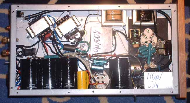
And the inside of a powersupply (they use 2pcs - one per channel in their top of the range Amp):
An externally hosted image should be here but it was not working when we last tested it.
More info from their website and in the various reviews posted there:
http://www.borderpatrol.co.uk/
Finally, if you insist on fitting all iron onto one chassis you might have a look aat how I did it when I chassis and some of the Transformers of the DIY HiFisupply "Billie" amplifier to my own design (which is very similar to SJS).
First a Photo showing the original positioning of Mains Transformer, Output and first Powersupply choke. Note orientation of these transformers, the Output is rotated so that it's main magnetic axis points int a direction 90 degrees opposed to that of the mains transformer and the choke is also oriented to minimise magnetic coupling:
An externally hosted image should be here but it was not working when we last tested it.
I kept the original Transformers but added below the chassis two more Supply Chokes (one for HT and one for the heater supply) as well as two signal chokes, one operating as gridleak choke and the other as anode-load. I found this scheme (Grid & Anode Choke plus coupling cap) subjectively better than some seriously expensive IT's I tried:
Edit - link does not seem to work as inline, try this:
http://www.jogis-roehrenbude.de/Leserbriefe/TH-Loesch-Amp/LadyDay-chassislayout.jpg
Again, observe how the chokes are oriented. The ones mounted on the side of the chassis and rotated out of the magnetic axis of the maions transformer are the signal ones. The two under the chassis at a 45 degree angle are supply chokes, both are the chokes that handle comparably little AC currents and thus have a low magnetic field level.
BTW, the 4 big black cans are the Polypropylene Powersupply Capacitors, the two silver boxes contain homemade "block" capacitors using multiple lower value MKT Film capacitors paralleled and potted in wax to give high value, non polar cathode bypass capacitors. The very "chaotic" looking resistor array is a result from threedimensional layout aimed at making all current loops to have the minimal possible length and is INTENTIONAL btw.
For reference, the resulting amplifier has < 100uV output noise, this being purely magnetic coupled - a result of the chassis being magnetic steel (hint - use non-magnetic cahssis materials, it would have lowered my hum further), or in other words a Signal/Noise ration of -92db unweighetd, referred to 1Watt/16Ohm or -100db referred to nominal output (7 Watt @ 3% THD).
I hope the above helps.
Sayonara
That is great input. I had seen the BorderPatrol amp with separate PSU and was considering that myself. With the SJS design the PSU is a considerable investment. Is the cost of dual PS worth it or could I get away with a Single? Aiming for the best quality I can achieve.
The PSU has 6 lumps of Iron in it so cost is high. If I build two PSUs then I will need two cases for those. If I use two would I be better off putting all the High Voltage supply in one box and perhaps sharing the Power TFR and the Heater supplies etc in the other - again sharing a TFR or do I build one per monoblock.
Thanks
Ralf
Konnichiwa,
I PERSONALLY would feel that Dual is better. Mains Transformers and chokes are not THAT expensive compared to good quality output and interstage transformers, so I'd say - go for dual.
You can house both channels of the supply in one case, nor does the case have to be conventional (how about a tower shape?). Border Patrol makes commercial add on supplies for other amplifiers and they (naturally) use the same case for their other supplies, neccesitaing two chassis and two supplies for their "big" amplifiers, also, two smaller supplies make shipping easier.
I'd say that this depends mostly on how you get the transformers for your supplies. If you have a custom mains transformer wound you might wish to consider the kind border patrol uses themselves, like this:
515-430-280-0-280-430-515 @250mA,
120-0-120@30mA,
3.15-0-3.15@1.5A, 5-0-5@4.5A,
5-0@3A, 6.3-0@1A, 6.3-0@1A.
With such a transformer you could also specify sectioned windings, electrostatic screens and a "low flux" (meaning more primary turns than usual) transformer, plus stacking the core laminations witha distributed airgap to reduce external magentic field and increase the transformers tolerance to DC offset on the mains. Adding a few low voltage windings usually will not increase the price all that much. Then obviously Dual Mono Chassis for the supply suggest themselves.
If you rely on using off the shelf transformers for HT you will find that you are short of quite a few low voltage windings and that you require a lot of "off shelf" low voltage transfformers. Then a split into High Voltage and low voltage chassis may more sense.
I would recommend however to have your mains transformers custom wound. Get them to wind the secondary windings on the inside of the former, output valve heater winding should be the first winding going on, with the primary on the outside (better coupling). Ask them to use more turns and a larger core than common (lower flux), to stack the laminations in blocks of 4 instead of interleaving 1:1 (increases Transformers tolerance against DC on the mains) to wind the primary fully "balanced" like an audio transformer (for maximised common mode rejection). Also ask to have electrostatic screens between primary and all secondaries and between the rest of the secondaries and the windings supplying the heaters for driver and output valve included.
If you can get the chokes custom made ask them to be wound for very low (parasitic) capacitance, this isoften called "wideband" choke. You will be surprised by the difference such measures make when compared to "cooking" type Iron.
Sayonara
DVDHack said:With the SJS design the PSU is a considerable investment. Is the cost of dual PS worth it or could I get away with a Single?
I PERSONALLY would feel that Dual is better. Mains Transformers and chokes are not THAT expensive compared to good quality output and interstage transformers, so I'd say - go for dual.
DVDHack said:If I build two PSUs then I will need two cases for those.
You can house both channels of the supply in one case, nor does the case have to be conventional (how about a tower shape?). Border Patrol makes commercial add on supplies for other amplifiers and they (naturally) use the same case for their other supplies, neccesitaing two chassis and two supplies for their "big" amplifiers, also, two smaller supplies make shipping easier.
DVDHack said:If I use two would I be better off putting all the High Voltage supply in one box and perhaps sharing the Power TFR and the Heater supplies etc in the other - again sharing a TFR or do I build one per monoblock.
I'd say that this depends mostly on how you get the transformers for your supplies. If you have a custom mains transformer wound you might wish to consider the kind border patrol uses themselves, like this:
515-430-280-0-280-430-515 @250mA,
120-0-120@30mA,
3.15-0-3.15@1.5A, 5-0-5@4.5A,
5-0@3A, 6.3-0@1A, 6.3-0@1A.
With such a transformer you could also specify sectioned windings, electrostatic screens and a "low flux" (meaning more primary turns than usual) transformer, plus stacking the core laminations witha distributed airgap to reduce external magentic field and increase the transformers tolerance to DC offset on the mains. Adding a few low voltage windings usually will not increase the price all that much. Then obviously Dual Mono Chassis for the supply suggest themselves.
If you rely on using off the shelf transformers for HT you will find that you are short of quite a few low voltage windings and that you require a lot of "off shelf" low voltage transfformers. Then a split into High Voltage and low voltage chassis may more sense.
I would recommend however to have your mains transformers custom wound. Get them to wind the secondary windings on the inside of the former, output valve heater winding should be the first winding going on, with the primary on the outside (better coupling). Ask them to use more turns and a larger core than common (lower flux), to stack the laminations in blocks of 4 instead of interleaving 1:1 (increases Transformers tolerance against DC on the mains) to wind the primary fully "balanced" like an audio transformer (for maximised common mode rejection). Also ask to have electrostatic screens between primary and all secondaries and between the rest of the secondaries and the windings supplying the heaters for driver and output valve included.
If you can get the chokes custom made ask them to be wound for very low (parasitic) capacitance, this isoften called "wideband" choke. You will be surprised by the difference such measures make when compared to "cooking" type Iron.
Sayonara
I worked for the local power authority as an engineer and I'm sure when we speced out transmission Transformers for the 275KV lines we didn't have that many specific requirements 
I'll ask my Transformer guy if he actually knows how to wind them in the fashion indicated.
Thanks for the input.
Can I assume from the feedback that the issue of magnetic coupling is more important between the PSU and the IT and OPT TFRs? Or will I still need to be careful with the placement of the TFRs and Chokes in the PSU?
Regards
Ralf
Konnichiwa,
True. But due to the ill conceived interfaces in audio and due the comparable nonlinearity of audio circuits care must be taken to keep any noise and related problems riding on the mains on the primary side of the transformer, especially with the levels of RFI from Long Wave to GHz floating around in modern countries.
Also, domstic mains supplies are often distorted, giving them what amounts to a DC offset. In transformers not designed with that in mind you get reduced efficiency, excessesive heat and noise etc....
Yes, it is MORE importatnt in Output and especially Interstage transformer.
It certainly does no harm to follow best practice and rotate the various chokes and transformers through the various degrees of freedom to reduce magnetic coupling as much as can be managed.
Sayonara
DVDHack said:I worked for the local power authority as an engineer and I'm sure when we speced out transmission Transformers for the 275KV lines we didn't have that many specific requirements
True. But due to the ill conceived interfaces in audio and due the comparable nonlinearity of audio circuits care must be taken to keep any noise and related problems riding on the mains on the primary side of the transformer, especially with the levels of RFI from Long Wave to GHz floating around in modern countries.
Also, domstic mains supplies are often distorted, giving them what amounts to a DC offset. In transformers not designed with that in mind you get reduced efficiency, excessesive heat and noise etc....
DVDHack said:Can I assume from the feedback that the issue of magnetic coupling is more important between the PSU and the IT and OPT TFRs?
Yes, it is MORE importatnt in Output and especially Interstage transformer.
DVDHack said:Or will I still need to be careful with the placement of the TFRs and Chokes in the PSU?
It certainly does no harm to follow best practice and rotate the various chokes and transformers through the various degrees of freedom to reduce magnetic coupling as much as can be managed.
Sayonara
DVDHack said:With the SJS design the PSU is a considerable investment. Is the cost of dual PS worth it or could I get away with a Single?
Ralf,
Consider the technique of splitting the PSU into separate legs.
This seems to work well with a two stage PSU, where the first stage is common, feeding two LC stages in parallel for left and right channels.
For a typical cct see the PSU of my 'Nina' preamp on this board.
Compared to a single PSU, there is only one additonal choke and cap so the oncost is not massive.
It appears to give highly effective isolation. Any reaction on one channel has to get through two chokes and past three caps before getting to the other channel. Remember, channel isolation is only really important at medium to high frequencies, where chokes are extremely effective isolators.
Highly recommended!
Especially as part of a well designed two pi filter ....
For many years I used a VERY similar amplifier system (my "Old Faithfuls") but with STC 3A/167Ms (UK equivalent of WE437A) driving self-biased RCA UX-245s via SJS it102s.
The first LC sections of the choke-input power supplies were shared between channels and were located in separate boxes.
Each amplifier had it's own LC sections "on board" and the result was a very quiet amp (over 100+ dB/W speakers) and an excellent sonic presentation.
Consequently I am an advocate of the multi-box amplifier approach.
These type of amps are VERY good if executed thoughtfully with quality components.
Brian.
Hello Ralf
I used the largest Maplin ali boxes for the PSUs so only had room for the first section. I used old wooden lab equipment boxes with copper top plates for the amps and the two chokes, IT and OPT fitted snugly inside.
I find the shared first section topology appropriate for choke input since doubling the current allows halving the inductance.
Brian.
Konnichiwa,
You did ask Brian, but I might have some relevant points.
It has been my experience that when using external PSU's (power- and/or preamps) all the final PSU Cap's belong into the Amp chassis, with a short current loop excluding added connectors. The difference is quite audible.
I tend to like 8-Pole speakon or if more connections are required the really expensive and heavy duty 2-Row style connectors (look similar to Printer Centronics Plug but are rated at 500V and have usually 16 Connections).
Sayonara
You did ask Brian, but I might have some relevant points.
DVDHack said:I was thinking separate boxes but why did ypou mount the last LC section on the Amp chassis.
It has been my experience that when using external PSU's (power- and/or preamps) all the final PSU Cap's belong into the Amp chassis, with a short current loop excluding added connectors. The difference is quite audible.
DVDHack said:What connectors did you use to take the PS to the Chassis? There are a lot of connections.
I tend to like 8-Pole speakon or if more connections are required the really expensive and heavy duty 2-Row style connectors (look similar to Printer Centronics Plug but are rated at 500V and have usually 16 Connections).
Sayonara
how about the high voltage version of Cliffcon from Cliff Components? available in 4- and 8-pole versions.
these are used by World Audio Design in their kits.
these are used by World Audio Design in their kits.
An externally hosted image should be here but it was not working when we last tested it.
An externally hosted image should be here but it was not working when we last tested it.
- Status
- This old topic is closed. If you want to reopen this topic, contact a moderator using the "Report Post" button.
- Home
- Amplifiers
- Tubes / Valves
- SJS SE108Mk2 Amplifier layout.