question: The source follower (irf720) need grid-gate stopper
Yes, like tubes (which they resemble), FETs need gate stoppers. A 1 Kohm carbon comp. part should be quite adequate on an IRF720's gate.
Depletion FETs as Source Followers
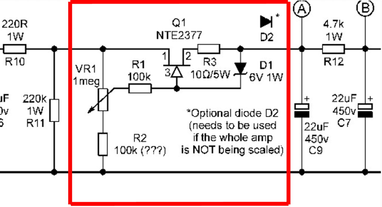
I adapted a K&K cascode depletion CCS board (IXYS IXTP01N100D and DN2540) to use a cascode source follower to drive the EL519 (A2) in my venerable EAR 859 amp. I added back to back (important) 15V zeners. It replaces the PCC88 cathode follower. I built the PCB into an adapter socket so I can use the valve or swap in the FETs. Been using the FETs for 2--3 years now with no issues and I routinely turn off (and on) my amp when not in use.
Everyone thinks the source follower sounds "better" but each to their own.
tim
Hmm... with the following valve preheated the coupling cap could have a low impedance charging path into the grid (does it have much of a grid stopper?), which will pull the MOSFET source down to a low voltage while the current is highest. Possibly pushing the MOSFET momentarily outside its SOA? Just a thought.Merlin, yes; heaters switched on first followed by +285 and -15 together.
I adapted a K&K cascode depletion CCS board (IXYS IXTP01N100D and DN2540) to use a cascode source follower to drive the EL519 (A2) in my venerable EAR 859 amp. I added back to back (important) 15V zeners. It replaces the PCC88 cathode follower. I built the PCB into an adapter socket so I can use the valve or swap in the FETs. Been using the FETs for 2--3 years now with no issues and I routinely turn off (and on) my amp when not in use.
Everyone thinks the source follower sounds "better" but each to their own.
tim
The original desing of my amp don t use cathode follower and drive directly the 6c33 with pentode 6ac7 (6sj7) in my case when I use the Source follower I think that the sound is better than before but I need to listen more time to be sure. This weekend I will change to dn2540
No that shouldn't matter.Is it important whether the gate stopper and protection zener are in series or parallel?
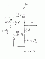
A 300 ohm stopper wouldn't limit the charging current very much. You would have to put a small resistance between the MOSFET source and zener to create a definite soft limit, e.g. like in this image:
Just in case you were asking whether running two zeners in opposed series or opposed parallel with each other makes a difference - YES. A Zener clamps voltage to its zener voltage in one direction, and to a diode drop (about 0.7V) in the other! So the pair should be in opposed series if you want to clamp the voltage within the zener's voltage (and an additional 0.7V). Otherwise, it will just be the same as running two regular diodes in opposed parallel, clamping to within 0.7V.
Well I'm only speculating about the failure mechanism, but if that were the case then yes, a slow ramp would help.Thank you Merlin; is the implication then that the abrupt appearance of the high voltage with preheated valves is a bad idea in this case? Would a slow ramp-up remove the problem?
bwaslo; actually I was asking whether it made any difference which end of the gate stopping resistor the zener is connected to but it's good that you brought up the topic of using two back to back-is it common practice?
In general I have found it frustrating that considering how common mosfet failure is, it seems difficult to find detailed and definitive information on how to avoid it. I was disappointed that, for instance, Morgan Jones included nothing on the topic in his otherwise excellent most recent edition of "Building Valve Amplifiers".That impression is strengthened by reading the confession by Sy earlier in this thread that he and the author put a quantity of depletion mosfets to death while searching for suitable source-follower candidates.
In general I have found it frustrating that considering how common mosfet failure is, it seems difficult to find detailed and definitive information on how to avoid it. I was disappointed that, for instance, Morgan Jones included nothing on the topic in his otherwise excellent most recent edition of "Building Valve Amplifiers".That impression is strengthened by reading the confession by Sy earlier in this thread that he and the author put a quantity of depletion mosfets to death while searching for suitable source-follower candidates.
A single zener is usually used for Mosfet protection. Assuming an enhancement mode N-channel, the cathode goes to gate, anode to source - in an analog circuit you shouldn't need the gate to go negative wrt the source, so the 0.7V clamp that direction would be ok. For depletion N-channel, a regular diode connected with cathode to source has worked for me (so far, anyway. I've not been at hi V source followers as long as many folks here).
zeners
From my poor knowledge I understand that with enhancement FETs a single protection zener is ok, but with depletion FETS back to back (or face to face) zeners are safer.
I also understand that the zener should connect between the gate stopper and the gate.
But I do admit I know SFA.
best
tim
From my poor knowledge I understand that with enhancement FETs a single protection zener is ok, but with depletion FETS back to back (or face to face) zeners are safer.
I also understand that the zener should connect between the gate stopper and the gate.
But I do admit I know SFA.
best
tim
blowing up FETs
JC Morrison wrote
"after a great deal of trouble driving the output stage with the current feedback driver stage shown above, i had to back up and get some help… 2 quick conversations with morgan jones and frank blöhbaum (at etf) helped enormously. i blew up a bunch of fancy depletion mode mos, and normal run of the mill hexfet enhancement mode mosfets too. it was hard to see what the failure mechanism was (morgan was extolling the virtues of inexpensive digital oscilloscopes for the ability to record events… i guess now i have one on my christmas wish list). it eventually turned out to be the gate charge and the extremely high impedance of the gM amp (the C3g stage)."
I dunno if that is of any help to anyone.
And please don't tell JC I've been quoting him here.
best
tim
I think Jesus would be OK with it.And please don't tell JC I've been quoting him here.
")
After looking at some of the posts here, I thought I would chime in with what has worked for me so far.
The DN2540 and its variants are wasted as direct emitter followers on their own (limited availability, high capacitance). they are eminently suitable as constant current source loads for an advanced source follower driver with lower distortion (current source source load) than the simpler implementation with a resistive source load.
The Supertex (and similar devices from Ixys) are best suited for a current source load for a small, low capacitance enhancement mode mosfet (the smallest you can find in a suitable package and voltage rating).
Whatever you chose for the top device in this scheme, it needs to be protected with a pair of back-to-back zeners from gate to source. You essentially need the smallest mosfet you can find with a 500+ Vd rating for the topside fet. Small device = low capacitance. Of course, you could short-circuit some of these considerations by using the same fet as a top-side driver with a bottom-side current source using a ring-of two source using the same mosfet and an NPN bipolar transistor.
With CCS need or not source follower
Well the next step is to remove the 6ac7 running as pentode with source follower and change to 6sn7 in cascade both anodes with CCS to drive the 6c33
With CCS 10m45s or dn2540 Mu follower to 6c33 need or not source follower? What will be the 6sn7 output impedance with CCS.
Well the next step is to remove the 6ac7 running as pentode with source follower and change to 6sn7 in cascade both anodes with CCS to drive the 6c33
With CCS 10m45s or dn2540 Mu follower to 6c33 need or not source follower? What will be the 6sn7 output impedance with CCS.
Wrenchone is probably right
Hi
I would guess Wrenchone is probably right.
"The DN2540 and its variants are wasted as direct emitter followers on their own"
On their own might be the key. In a cascode they may work better--I don't know enough to be sure--but in my case the cascode of depletion fets seem to do very well. Very well.
However, the main reason I used them is its easy to use them in a cascode without additional biasing, and most importantly the wee K&K board allowed adaption to a 9 pin socket quite easily.
When I rebuild the amp I'll adapt the very versatile Gary Pimm CCS with 820s to try as a source follower driver for A2.
tim
As I mentioned in my previous post, you don't really need depletion mode fets if you're trying to make a current source loaded source follower. The attached schematic shows a possible circuit utilizing a ring-of two current source to load a source follower for low distortion. The mosfet in the ring-of two could be also replaced with a bipolar transistor - there are many candidates, but the MPSW42 comes to mind, and there are several TO-126 devices that are even better.
A stopper resistor is definitely needed fro the top mosfet. I usually start with 100 ohms. 1k works fine, but that might be overkill. I'm not certain if the stopper is needed for the mosfet in the ring of two. I'd try it without one first.
If you use a bipolar ring of two instead, a stopper can actually make matters worse.
Attachments
- Home
- Amplifiers
- Tubes / Valves
- Source follower IRF720 or DN2540