I'm finishing up the breadboard design of the first "serious" tube amp I've worked on, LTP to P-P, using 12T10 compactrons. There more in some of my other posts if anyone cares, but my thinking has taken a bit of a turn, and before I commit to building this in a nice cabinet I'd like to check on something.
To impedance match to a typical "ipod"-type music player I'm using a 600:10K transformer directly coupled to the grid of the LTP input side, with a 3.3K resistor in parallel to the high impedance (grid) side. Behaves well enough, and I'd go with it except that looking at the transformer last night and considering that it's center-tapped (both windings) I began to wonder if I should try something different.
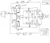
I've attached a schematic (cribbed from one that I found on the web, original by Pete Millet, but I think I "anonymized" it enough to respect his copyright) of what I'm thinking about. Same tubes, different config.
I'll lose the ability to use NFB, but maybe there's something gained here. It is worth trying?
Thanks
To impedance match to a typical "ipod"-type music player I'm using a 600:10K transformer directly coupled to the grid of the LTP input side, with a 3.3K resistor in parallel to the high impedance (grid) side. Behaves well enough, and I'd go with it except that looking at the transformer last night and considering that it's center-tapped (both windings) I began to wonder if I should try something different.
I've attached a schematic (cribbed from one that I found on the web, original by Pete Millet, but I think I "anonymized" it enough to respect his copyright) of what I'm thinking about. Same tubes, different config.
I'll lose the ability to use NFB, but maybe there's something gained here. It is worth trying?
Thanks
Attachments
"Why use an input transformer in the first place?"
Hmmm...
Because I'm curious about how it might work?
Because I have this fascination for endlessly soldering and de-soldering things?
Because I needed one for a project awhile back, and so of course I bought 10 of them because I found a great bargain to park next to the last 42 "great bargains" on my shelf?
Because I tried to get my wife to wear them as "steampunk" earrings and found her oddly uninterested in the idea?
I'll lose the ability to use NFB, but maybe there's something gained here. It is worth trying?
You can save a HT power transformer! Alas, it's not allowed to be discussed here. Other than that, i can't think of anymore reason to do it. Does it have wide enough bandwidth for audio?
geezertron,
It's worth trying, I use Edcor's little 10K/10K to do this (WSM series if that is the smallest they make). If you have an insulated input jack you can take your "+" signal from the center pin and your "-" from the outside jack and listen first to see if adding the transformer input is an improvement. And you can also move your input trans behind your first stage pair and listen to that if you have the voltage/power overhead in your transformer.
Matt
Take a look for the ST70 upgrade kit from kankaudio.com. It employs an input transformer for this purpose.
Johnny
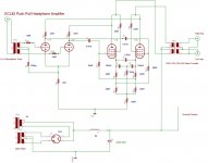
The K & K kit uses a 1:1 transformer (with the option of 1:2 for 6db gain) in basically the same circuit to drive the grids of both halves of a 6n23P which then each drive a triode connected el-34.
It works well and sounds great...even with the cheaper LL1591 transformers.
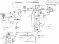
I also just bought some 12T10's to try this topology (see attachment). Sorry for the bad drawing but it is a simple PP with LTP front end, blumlein/garter bias on the power pentode (can also be achieved with CCS), and cross-coupled (local or partial) feedback.
I will also try a ccs on top of the first pentode with a paralleld load resistor (see website Gary Pimm for details).
I will also try a ccs on top of the first pentode with a paralleld load resistor (see website Gary Pimm for details).
Attachments
The use of input trafo for a push pull is the best way to have the perfect splitter, in my opinion.
I have used the 3575 Sowter for this purpose.
There is also a double aspect; first the possibiliti to use the unbal and balance connection and second the ground separation from source.
For feedback the best solution is to have a secondary of output trafo with a central ( connected to ground) but there is a way to use also a normal secondary.
If you disconnect one end from ground the secondary is floating and balanced; at each end you can connect a resistor of 47-100 ohm 3w to ground.
The you can take the Feedback signal from each end to first stage with a proper resistor.
Bye
Walter
Last edited:
Everyone, thanks for all the info.
Funk1980, I probably owe you a little better reply...
(With reference to the attached image.) Most little music players need to see a fairly low impedance on the headphone output. Config #1 was where I started, but if you make R1 small it hurts low frequency response. Making the C1 large unbalances the LTP, I suspect because it allows a low impedance path through R2, even though it's a high resistance. I'm not yet experienced enough to understand all of the details of an LTP, but I know by measurement this is the case, and it's hard to compensate for without changing several component values.
Originally I put the transformer on front of the RC input (#1), allowing me to raise the value of R1. But eventually I realized I could just go to Config #2 and get the same effect with less components. It seems to work at least as well.
An additional bonus is the voltage gain in the transformer allows the music player to drive the amp to full output without turning the volume on the player all the way up. In fact, even at full volume some players couldn't drive the amp at full power with the original config, setting aside the poor low frequency response.
With the transformer as shown in #2 the frequency response rolls off -3dB at 40Hz, which is good enough for the tiny speakers I intend to use. Without it the response was much worse, starting to roll off well above 100Hz depending on the values of R1 and C1.
Attachments
Jaap - Had a little more time to look just now. What is the benefit of grid-leak bias in this type of circuit? My first instinct would have been to just run the center of the transformer to ground and use cathode bias, and #2 would have been to ground the cathode and connect the center to a negative bias. I'm familiar with grid leak bias from old (1920's era ) radios I've repaired or replicated, and always regarded it as kind of old-fashioned and not a very exact way to bias.
Jaap - Had a little more time to look just now. What is the benefit of grid-leak bias in this type of circuit? My first instinct would have been to just run the center of the transformer to ground and use cathode bias, and #2 would have been to ground the cathode and connect the center to a negative bias. I'm familiar with grid leak bias from old (1920's era ) radios I've repaired or replicated, and always regarded it as kind of old-fashioned and not a very exact way to bias.
It is a design of Shoog and there has been some discussion on this board about it. Perhaps you can use the search function or P.M. him. I was just a copy cat
Thanks for the pointer. Leaving out all of the details what I took away is that it works well for small input signals in circuits that require very high input impedance. I do know is the same reason it works so well in detector stages for old-style tube radios, never thought about it in other contexts. But it's not going to work for what I have in mind. If I get the time this weekend I'll build something and see how it comes out.
- Status
- This old topic is closed. If you want to reopen this topic, contact a moderator using the "Report Post" button.
- Home
- Amplifiers
- Tubes / Valves
- Transformer input for P-P