Hi all,
I have been working on an hybrid hi fi amp with Mosfets as an output stage and a valve driver.
The big problem I struggle for is to drive the Gates capacities of the Mosfets. The doc says they are about 1nF each, so I can say that the driver's loading is about 2 nF and some 3 to 5 K resistive.
I tried all sorts of opamps: no success. Plus oscillations.
I tried the hybrid MAsfet/valve cascode with great success and am using it.
However, I would like to try now the SRPP or the Cath follower.
There, no success.
I have been messing with valves for some time and am aware of most of the basics.
SRPP: nothing comes out. I cannot find what the book says, changing the value of Rk does nothing to the global balance: I should have half the +V at the Anode of bottom valve but noway. Can't understand why.
Cath follower: there, I have a rather ok result but it attenuates the signal way too much (about -30%).
Everything is properly under control and according to the book, but I can't get over this problem.
So a few questions for you experts:
- How come this attenuation ?
- Do you have highlights about the true driving possibilities of the cath follower ? I read that the output impedance is in the dozens of Ohms but see on the scope that the signal decreases if the Load comes under 10 K !
My Mosfet driving problem can be imagined as being a 4 KOhm with 2,2 nF paralell.
My signal amplification is with an ECC88 (180 V PS, 5 mA, anode R= 18K, Vg= -2V, of course decoupled), the cath follower is with a 5963 (analoguous to ECC82 or 12AU7) with 10 to 15 mA. Rk=18K and Rpol is 1k series to Rk.
Thanks a lot !
The gain of the cathode follower is >1 always or worst.
Rise the load of the ECC88, and put a cap on the cathode of this valve. The best gain of the ECC88 in srpp is 30 that is the µ of the valve. But you gonna take this amount with the cap on the cathode.
Does is direct coupled the SRPP with the CF? Send a circuit of the amp.
Best Regards
Rise the load of the ECC88, and put a cap on the cathode of this valve. The best gain of the ECC88 in srpp is 30 that is the µ of the valve. But you gonna take this amount with the cap on the cathode.
Does is direct coupled the SRPP with the CF? Send a circuit of the amp.
Best Regards
Cath follower: there, I have a rather ok result but it attenuates the signal way too much (about -30%).
- How come this attenuation ? My Mosfet driving problem can be imagined as being a 4 KOhm with 2,2 nF paralell.
Do you have gate resistors on each of the fets, and what value?
Your source has to be less than 1k impedance to drive this with a 70k bandwidth and less than 2dB loss.
Last edited:
The gain of the ECC88 is alreay at its max and I do get a mu = 30 with perfect signal up to 50 khz with everything excellent.
The Cat Fol is coupled via a cap (0,22 uF).
The Mosfets indeed have a Gate resistor (470). The bias system is : (+V)---4,7K----10K---10kadj---10k---(-V) and the gates take in on both sides of the adj 10K. This is standard and works. Comes from Broskie 's Tube CAD.
My current hybrid Mosfet has a much lower values bias system with a 1K between gates. Works beautyfully.
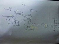
I have uploaded a (rather dirty but valid,) schematic of what I have now running in my current experiments. Please apologize for the bad quality !
I agree with the need for very low Zout, theoretically I should have it with the Cath Foll, but practically, far from it. Therefore my questions...
Thanks again !
The Cat Fol is coupled via a cap (0,22 uF).
The Mosfets indeed have a Gate resistor (470). The bias system is : (+V)---4,7K----10K---10kadj---10k---(-V) and the gates take in on both sides of the adj 10K. This is standard and works. Comes from Broskie 's Tube CAD.
My current hybrid Mosfet has a much lower values bias system with a 1K between gates. Works beautyfully.
I have uploaded a (rather dirty but valid,) schematic of what I have now running in my current experiments. Please apologize for the bad quality !
I agree with the need for very low Zout, theoretically I should have it with the Cath Foll, but practically, far from it. Therefore my questions...
Thanks again !
Attachments
I think for hybrids , for the sake of simplicity and good sound , you really need to use a mosfet with lower gate capacitance such as the Semisouth 085 , 2SK1085 or RD16HHF1 . I have used a 4P1L driver in my hybrid mosfet follower amp , this has much lower Ra than ECC88 and makes a very decent sounding driver for mosfets
316a
316a
Hi all,
The big problem I struggle for is to drive the Gates capacities of the Mosfets. The doc says they are about 1nF each, so I can say that the driver's loading is about 2 nF and some 3 to 5 K resistive.
Also, as you have this low input impedance if you have 500R-1K resistor in series to the cathode of the follower you get lower gain. Taking the output directly from the cathode should increase the gain of the cathode follower.
Resuming: Cathode follower, use the same ECC88, more S; Use connection tied direct to the pin 8 or 3; Couple directly the valves and If the CF is another ECC88 this voltage is correct. Another issue, the ECC88 in cathode follower is enough for normal lateral mosfet, the 4P1L is fine but in this case is an unnecessary complexity.
Best Regards for the rest of the gentlemen
Best Regards for the rest of the gentlemen
Last edited:
Thank you everyone. Lots of interesting clues.
I will try immediately to convert to DC coupling.
The V amp has a 2volts grid pol and it gives some 80 V on the Plate, the ECC is fine with this value. I don't have V gain problems, only I out impedance is too high. Happy to read that the ECC88 is ok for lateral mosfets.
I have chosen the ECC82 (5983) as Cat follower because it can draw much more current that ECC88.
I use as Mosfets the ALFET series (ALF08NP), with 750 pf Gate capacitance and a need for 2,5 mA to drive them (according to the doc). They come in a one case 5 pins, paired N and P type. Runs superb.
Thanks and best regards to all.
Whatever gave you that idea?I have chosen the ECC82 (5983) as Cat follower because it can draw much more current that ECC88.
My choice for 5983 is that I use it now in my current set with huge pleasure: neutral, fast, perfect sound in my opinion.
Luckily I have a bunch of those. I only have a few ECC88 and would prefer keeping them for the V amp needs.
The hybrid diagram is partly on my photo. It is a personnal schematic. The values are lower however since the current Mu Follower with Mosfet as a load (upper triode) gives out all mAmps it needs. I think all valve would perhaps improve it still !
Now, here are some results:
- Direct coupling improved enormously the result: I feed the Cat fol with a 23 Vpk signal (1V pk tot he ECC, 23 Vpk out of it. Enough for my needs) out of the ECC88 directly on the 5983 grid.
I get 20 Vpk with a 10K and 2,2 nf load, simulating the mosfet grids.
- quality of the signal is just excellent. Slew rate from 0 to 20 V in 50 usec. Squares perfect, no overshoot whasoever. This was verified at 35 kHZ 20 Vppk.
Now, I still don't understand why the 10K load is more or less the minimum accepted by the whole system. I am not even sure the Mosfet grid load will not be still lower.
Why is the Cath foll Zout not closer practically to the few tens of ohms usually announced for cath folls ?

Thanks a lot again !
Luckily I have a bunch of those. I only have a few ECC88 and would prefer keeping them for the V amp needs.
The hybrid diagram is partly on my photo. It is a personnal schematic. The values are lower however since the current Mu Follower with Mosfet as a load (upper triode) gives out all mAmps it needs. I think all valve would perhaps improve it still !
Now, here are some results:
- Direct coupling improved enormously the result: I feed the Cat fol with a 23 Vpk signal (1V pk tot he ECC, 23 Vpk out of it. Enough for my needs) out of the ECC88 directly on the 5983 grid.
I get 20 Vpk with a 10K and 2,2 nf load, simulating the mosfet grids.
- quality of the signal is just excellent. Slew rate from 0 to 20 V in 50 usec. Squares perfect, no overshoot whasoever. This was verified at 35 kHZ 20 Vppk.
Now, I still don't understand why the 10K load is more or less the minimum accepted by the whole system. I am not even sure the Mosfet grid load will not be still lower.
Why is the Cath foll Zout not closer practically to the few tens of ohms usually announced for cath folls ?
Thanks a lot again !
When driving the 3k load, the ECC82 has an open-loop gain of perhaps 5, and an open-loop output impedance of about 5.5k.why should I get 500 Ohms and practically do I get as much as 10 K !
You have a 560k grid leak, and a 5k source impedance from the ECC88, so the feedback fraction is 5/(5+560) = 0.009.
The feedback factor is therefore 1+0.009*5 = 1.045
You should therefore expect the closed-loop output impedance of the ECC82 to be 5.5k/1.045 = 5.26k.
Lesson: The ECC82 is rubbish at driving a 3k load. You need an ECC88 or even a small power valve, and you need to use DC-coupling or fixed-bias to achive 100% feedback around the cathode follower.
Sorry Merlin, I don't understand your sums. What do you mean by "an open-loop output impedance of 5.5k"? A CF always has a feedback factor of 1. As I said, an ECC82 CF should have an output impedance somewhere around 500 ohms - not 5k. I agree that it won't be brilliant at driving a 3k load, but it should not be complete rubbish either.
The pic is invisible for me.
Dear french friend, could you make the question again?. One thing is the output load of the CF, the other is the load that you connect there that must be the higher for better sound. I you connect a high capacitive load like a mosfet you going to have an low load. The ECC88 is lower than ECC82 for this case.
Dear french friend, could you make the question again?. One thing is the output load of the CF, the other is the load that you connect there that must be the higher for better sound. I you connect a high capacitive load like a mosfet you going to have an low load. The ECC88 is lower than ECC82 for this case.
- Status
- This old topic is closed. If you want to reopen this topic, contact a moderator using the "Report Post" button.
- Home
- Amplifiers
- Tubes / Valves
- Cathode follower attenuates signal