Has anyone used the regular white solderless breadboards at higher (tube) voltages? How high? I can't find any that have any rating for pin to pin breakdown voltage. I believe most are made of ABS.
I've got a couple on order that I intend to test to breakdown, but they won't be here for a while.
I've got a couple on order that I intend to test to breakdown, but they won't be here for a while.
I've used those white breadboards you can buy these days to test switchmode power supply designs at line voltage (so 340V on the board)- and written off the boards. No because there was a voltage breakdown, but because the current though the relatively high contact resistance melted the plastic.
The old SK10 white breadboards made in the 1970's & 80', by Continental Specialties in Connecticut were quite a bit better, in all respects. I still have a couple. They've been used hundreds of times and are still as good as new.
What I use to breadboad tube designs on is something much better. I obtained some blank glass fibre board (ie same as PCB but without the copper) and drilled 1/4 inch holes all over it in a 3/4 inch spaced grid pattern. Then I got some GI wire and made a few dozen male and female springs. The males are sort of elongated side-squashed omega-shaped. The females are wound into a coil 2/3 inch high, a few turns at one end about 1/4 inch dia, 10 or so middle turns 1/3 inch dia, the other end a few turns back to 1/4 dia.
I push a male up thru the bottom of the drilled board, a female over the top down on the male. Because of the shape they lock into place. Then you can insert resistor and capacitor pigtails into the top, and the spring tension holds them in place and interconnects them.
I mount big things like transformers, big electro's tube sockets in a multi-hole test chassis originally invented by the British Broadcasting Corporation research department in teh 1950's. It is re-usable and the hole pattern is cunningly designed so there is always a hole to mount something, providing the layout is not too compact. Pots and meters mount on the sides. I keep a few tube sockets with wires attached so that I can wire them to the spring arrangments.
Last edited:
I've used them for various projects, transistor and small tube projects, that required over 200V. Even built a tube regen radio on one. The biggest problem I found was the capacitance between the contact rows is rather high and can interfere with some circuits.
What I did was to ground every other row of contacts using an external bus (not the one on the board). Nothing more than a stout piece of wire hanging off both sides with connections coming to it from every other row.
I suppose that if you wanted to do a complete job taking the back off the board and removing every other row of contacts would be better, but then you need to have some way of telling which rows are "dead". Maybe mark them with a sharpie?
I wouldn't use those plug boards. The resistance is high and the capacitance between rows is as well. I also don't care for arranging everything in rows...
Personally, I have a piece of scrap PCB material with holes drilled for tube sockets. The PCB copper is grounded and I just build the circuit point-to-point. I've prototyped all my amps that way. You can see an image here: http://www.diyaudio.com/forums/tubes-valves/164390-rfc-300b-driven-anode-follower-6j5-6sn7.html
Another example here: http://www.diyaudio.com/forums/tubes-valves/157453-6lu8-spud-request-comments.html
~Tom
Last edited:
The resistance and capacitance are issues, as it the insulation. The ones I had used a tacky paper backing that held all the contacts in place. The whole thing was screwed down to a piece of black aluminum. After a few years and a thousand or so insertions, the paper backing would wear thin, and bang. The B+ shorts to the metal backing which BETTER be grounded.
The previously mentioned high capacitance made them generally useless even for low voltage digital circuits above a few MHz.
Back in the 60's there were large versions of the same concept with much wider row spacing designed for vacuum tube prototyping. They were made of clear plastic, possibly by DeVry tech. We had them in the technical high school that I attended in 1967 - 1970. I haven't seen one since.
Tom, I use pretty similar point to point technique for prototypes. Just exploring the possibility of something quicker and easier for when I try a bunch of different ideas or have to experiment with component values. Capacitance and high resistance are not a concern, voltage is. The breadboard would be used to try things like different CCS configurations, power supply circuits, etc. for initial feasibility and establishing operating points.
The origional SK10 breadbaord had a paper backing. Removing that was the first thing I did. I screwed the breadboards to a metal sheet "chassis" with a 3 sheets of cooking mylar between. You have no worries about breaksdown then.
The ones you can buy here now (made in Asia) have a double sided sticky tape backing, and come with an aluminium plate that you are supposed to stick the breadbaord to. I've always used the aluminium plates for something else, removed the sticky tape, and again attached them to my own metal chassis with cooking mylar separation as before.
The aluminium plates they come with them are 0.4 mm thickness and quite useful for making plates for my homemade air spaced variable capacitors.
Using plug boards for high voltage circuits is quite dangerous!
Occasionally unplugged wire with 400 - 600V is a source of deadly shock!
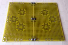
There is a plenty of PCB prototyping boards sold on eBay, I used them in the past.
Unfortunately, they are too thin (1.6 mm), too flexible (bend when you insert tube into socket), and for my projects were too small, assembly become to crammed and not convenient to modify / tweak.
So I after all I designed my own 180x110mm / 7.1x4.33", 2 mm double sided FR4, 5mm pitch, 3 universal socket placeholders (7 pin B7G, 9 pin noval B9A, octal, loctal B8G with small mod), and stackable with steel flanges, so its possible to prototype either 2 channel pre-amp, or 1 channel power amp with 2-board assembly.
Occasionally unplugged wire with 400 - 600V is a source of deadly shock!
There is a plenty of PCB prototyping boards sold on eBay, I used them in the past.
Unfortunately, they are too thin (1.6 mm), too flexible (bend when you insert tube into socket), and for my projects were too small, assembly become to crammed and not convenient to modify / tweak.
So I after all I designed my own 180x110mm / 7.1x4.33", 2 mm double sided FR4, 5mm pitch, 3 universal socket placeholders (7 pin B7G, 9 pin noval B9A, octal, loctal B8G with small mod), and stackable with steel flanges, so its possible to prototype either 2 channel pre-amp, or 1 channel power amp with 2-board assembly.
Attachments
Last edited:
Tom, I use pretty similar point to point technique for prototypes. Just exploring the possibility of something quicker and easier for when I try a bunch of different ideas or have to experiment with component values.
I generally find the plug boards to be significantly slower to work with than P2P circuits. The plug boards look great in theory but when working with components in rows, you end up spending half your life making little wire staples (or half your paycheck buying a kit of staples). But hey... Each to his own.
I remember seeing the plug boards in college. They were dissed by the professors and by the time I reached college, I'd been building circuits on home made PCBs and/or vector board for over a decade... I never saw the point of those boards. Not that I'm opinionated or anything...
")
Capacitance and high resistance are not a concern, voltage is. The breadboard would be used to try things like different CCS configurations, power supply circuits, etc. for initial feasibility and establishing operating points.
You can test CCSes at low voltage. The plug boards are fine for that. For establishing operating points on the tubes, I'd use a circuit simulator... At least the models I've messed with have been quite good for DC OP points.
~Tom
Last edited:
The plug boards look great in theory but when working with components in rows, you end up spending half your life making little wire staples (or half your paycheck buying a kit of staples).
~Tom
No and no
I've worked with breadboards for many years. Half of the time resistors ARE your "staples". I rarely make staples, I have a few dozen pieces of 22ga solid wire with stripped ends. They're reusable. Or use these, it doesn't get much cheaper:Arduino 65pcs Male to Male Solderless Flexible Breadboard Jumper Cables Wires | eBay
- Status
- This old topic is closed. If you want to reopen this topic, contact a moderator using the "Report Post" button.
- Home
- Amplifiers
- Tubes / Valves
- Breadboards and tube voltages