The tranbsformer inductance is too low. The dynamic anode resistance of the tubes is going to be about 300 ohms, so the amplifier bandwidth will be 3 db down at about 450 Hz.
Since the 6AS7 has an amplification factor of only 2, the signal voltage on the collectors of the drivers is going to be something like 50 V pk-pk at full output. So expect noticeable distortion from Early effect.
Since the 6AS7 has an amplification factor of only 2, the signal voltage on the collectors of the drivers is going to be something like 50 V pk-pk at full output. So expect noticeable distortion from Early effect.
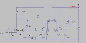
I have some space left on the PCB i designed and was wondering if there is anything i can add to the attached schematic that would improve the performance?
A simple resistor was deliberately chosen over CCS on the LTP's tail, so please don't suggest this.
1) Cascode LTP for the front end. This will improve open loop distortion performance by distributing the output swing over two BJTs instead of just the one. The bottom BJTs should also have emitter degeneration resistors equal to:
RE= 10re
Cascoding also helps combat Early Effect that will compromise BJT performance, both as amplifiers and CCS duty.
2) The 47uF DC isolation capacitor (C2) in the gNFB loop is way too small. This needs to be at least 680uF, and a premium like a Blackgate or Mundorf.
3) R8 and R10 should be equal. Otherwise, you're asking for a nasty DC offset. Even though DC isolated, this can still compromise the distortion performance of a BJT LTP.
4) The DC return resistor for the base of the input side should be bypassed with a small capacitor. Bases are a good deal more sensitive to incidental RF than VT grids, and will introduce more noise by detection.
Thank you all!
That transformer inductance is mostly my ignorance on how to model a transformer properly. I want to use 2K:8 transformer. What value should i use for L1, L2 and L3?The transformer inductance is too low.
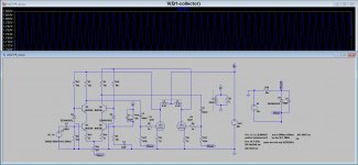
Can you show me example of cascode LTP? I came up with the attached schematic but i must be doing something wrong. Collector voltage on Q1 is relatively constant, which means the upper transistor is experiencing all the swings and i'm still having Early effect. Incorrect bias maybe? Tried increasing the zener diode to 33v but i end up with the transistors cutting off.1) Cascode LTP for the front end.
How so? 47uF with 1k equals around Cutoff Freq of 3.4Hz. Isn't this enough?2) The 47uF DC isolation capacitor (C2) in the gNFB loop is way too small.
Done. Realized this earlier when simulating but i forgot to change the value of R10 back to 47k.3) R8 and R10 should be equal.
How does one find the value of re? Came up with a value of 22R but this is random search on google.The bottom BJTs should also have emitter degeneration resistor
Attachments
The 6AS7 is a big triode designed for voltage regulation service, not audio power output. As such its's ra is about 300 ohm. Choosing a 2Kohm transfomer primary will result in gross inefficiency. The max anode swing for a +80V HT will be about 120 V p-p, so the output power will be only about 3 watts - barely adequate for quite listening with today's speakers - is this what you want? If you drop the transformer pri Z to about twice ra, (ie 600 ohm) you will get about 12 watts - not too bad for quite listening.That transformer inductance is mostly my ignorance on how to model a transformer properly. I want to use 2K:8 transformer. What value should i use for L1, L2 and L3?
The low frequency limit of power bandwidth is determined by the frequency at which the transformer inductive reactance drops to the working impedance level. The lowest fequency reproduced on CD's is about 20 Hz. Hence primary inductance should exceed 300 / (2PI x 20) ie 2.4 H. For an amplifier with a more normal tube selection and HT voltage, and thus using a 2 kohm primary, the inductance needs to exceed 16 H.
Failure to provide sufficient transformer inductance leads to severe distortion as the negative feednack tries to force the tube to do something it cannot do.
The swing on the lower transistor collectors should be minimal - that is the idea of cascoding. The lower transistors do not exhibit distortion due to Early effect because there is almost no collector swing. The upper transsitors also do not cause distortion due to Early effect because their collector currents are forced to be almost the same as the collector current of the lower transistors. The upper transistor base currents will be "distorted" but that doesn't matter.Can you show me example of cascode LTP? I came up with the attached schematic but i must be doing something wrong. Collector voltage on Q1 is relatively constant, which means the upper transistor is experiencing all the swings and i'm still having Early effect. Incorrect bias maybe? Tried increasing the zener diode to 33v but i end up with the transistors cutting off.
You are correct, sort of. You have chosen C4 and R12 to give the same cutoff frequency. This makes for instability. Do not correct the transformer inductance to also cutoff at 3.4 Hz - if you do you will have an oscillator, not an amplifier. The lower frequency limit must be set at one place only. In your revised (cascode driver) you have reduced the feedabck shunt to 220 ohm, the cap needs to increase proportionately.How so? 47uF with 1k equals around Cutoff Freq of 3.4Hz. Isn't this enough?
To ensure complete stability and get low distortion, make C4 and R12 cut off at the lowest limit of audibility, say 50 Hz. Choose the transformer to cut off at 1 fifth that (10 Hz), and C2 & R9 a bit lower agin, say 5 Hz.
Splendid.Done. Realized this earlier when simulating but I forgot to change the value of R10 back to 47k.
re for a bipolar transistor is approx 30 divided by emitter current in milliamps.How does one find the value of re? Came up with a value of 22R but this is random search on google.
If you don't mind me making a further comment:-
There seems to be a trend amongst beginners on diyAudio to rush into a SPICE simulation. SPICE is an exellent tool in the hands of someone who knows what he is doing. But it means you skip understanding how the circuit actually works. If you make the effort to work it all out manually with a simple calculator and paper you will gain a vastly better understanding of how the circuit actually works or doesn't work.
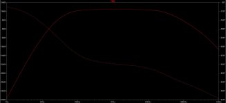
If you must use SPICE, why dind't you do a frequency response run? You would then have reliased the circuit you proposed has no bass response.
But if you had ignored SPICE and simply realised that the the transformer inductance has a low freq cutoff and used L = X/2Pi.f, you would not need to ask many questions.
Last edited:
Thanks again! I have a lot to learn from your response.
I realized this formula but knows not about how to model the transformer. Hence, i chose the primary inductance value to match the input signal frequency (1kHz) and the intended primary impedance. Hence, i end up with something like 0.1H --> (with 1kHz this gives around 628R from plate to center tap.
I did try using 6H+6H for the primary but it gave me confusing result.
I just found a transformer modelling tool made by one member here, will do more study and update this thread with what i learn.
If you must use SPICE, why dind't you do a frequency response run? You would then have reliased the circuit you proposed has no bass response.
L = X/2Pi.f
I realized this formula but knows not about how to model the transformer. Hence, i chose the primary inductance value to match the input signal frequency (1kHz) and the intended primary impedance. Hence, i end up with something like 0.1H --> (with 1kHz this gives around 628R from plate to center tap.
I did try using 6H+6H for the primary but it gave me confusing result.
I just found a transformer modelling tool made by one member here, will do more study and update this thread with what i learn.
I realized this formula but knows not about how to model the transformer. Hence, i chose the primary inductance value to match the input signal frequency (1kHz) and the intended primary impedance. Hence, i end up with something like 0.1H --> (with 1kHz this gives around 628R from plate to center tap.
I did try using 6H+6H for the primary but it gave me confusing result.
Why on earth 1 kHz? That is in the middle of the audio band (Ear response to freqncy is logarithmic). Don't you want any bass?
As I said, if you use a more corect value of transformer inductance, the other C & R consants in your circuit will make your amplifier into an oscillator. How SPICE reacts to that depends very much on what brand/implementaion of SPICE you are using, and how yoy set it up. Some will just give a stupid result. Some will refuse to converge and either lock up or give an error message. Some will correctly show oscillation.
If you make the cut-off frequency of all AC coupling points in an amplifier about the same, and apply negative feedback, you will have an oscillator. You will have an oscillator because at around the cutoff frequency, each C-R coupling contributes some phase shift. If the loop gain is greaster than unity at the frequency where the sum of all the phase shifts is 180 degrees, it will oscillate.
That is why you should ensure that the amplifier cutoff frequncy shoukd be determined AT ONE POINT ONLY. All other couplig circuits, cathode bypasses if used, and transformers, should cut-off quite a bit lower than this, so that the phase shift cannot exceed 90 degrees (in fact significantly less than 90 degrees) at the frequency at which the loop gain drops to unity.
I suggest you give SPICE a miss, untill you have learnt what formulas like X = 2.pi.f.L actually mean, instead of trying to apply them like a robot.
Having said that, if you want to continue with SPICE, just model the transformer as simple coupled inductors (but with sensible values) as you have done. That will be sufficient to get a simple amp like this working, if you run SPICE over a full freqncy range.
A more correct transformer model adds leakage inductance in series with each winding, shut capacitance on each winding, and interwinding inductance. But that is for later. Learn to walk before you attempt running and jumping.
There are some other non-optimal aspects of your circuit but they won't prevent it from working.
Thank you all!
That transformer inductance is mostly my ignorance on how to model a transformer properly. I want to use 2K:8 transformer. What value should i use for L1, L2 and L3?
For OPT primaries, you want Lpri= ~50H. This represents the point of diminishing returns. The idea behind a high L is so that the loadline under reactive loads doesn't open up too much. Nice straight loadlines (pure resistance) aren't seen in anything but RF work where you can "tune out" reactance. Reactive loads make for elliptical loadlines (for one frequency only) where the major axis is the resistive load. Insufficient reactance makes for more circular loadlines that dip into plate current cutoff prematurely. That makes for increased distortion. Good OPTs will give you the most L.
Can you show me example of cascode LTP? I came up with the attached schematic but i must be doing something wrong. Collector voltage on Q1 is relatively constant, which means the upper transistor is experiencing all the swings and i'm still having Early effect. Incorrect bias maybe? Tried increasing the zener diode to 33v but i end up with the transistors cutting off.
Like this Si-Lver Fox. Even though this is a SS design, the up front LTP would be the same.
"How so? 47uF with 1k equals around Cutoff Freq of 3.4Hz. Isn't this enough?"
For good LF stability, the usual rule is to make Xc= Rs/100 at the lowest frequency of interest.
"How does one find the value of re? Came up with a value of 22R but this is random search on google"
re= 26/IE (IE in mA)
Last edited:
For OPT primaries, you want Lpri= ~50H.
That will be excessive in this case. Usually in audio a tube with a higher ra is used with a much higher HT voltage. In such cases the transformer is working at an impedance of 2000 ohms or more.
For some reason BallPencil has elected to use a power regulator triode with a very low ra (~300 ohm). A very low amplification factor too, which is not going to help get low driver distortion. Perhaps he has a box of 6AS7's. So an inductance of a tenth of the usual value is quite sufficient. Using a more typical output transformer is likely to result in Joule power loss and restricted trebble due to leakage reactance being 10 times more significant at the low impedance involved here.
Truth be told, i want an amp with tube output without having to spend much on output transformers. This means using toroidal mains transformer which i realize has sub-optimal primary inductance for the typical tube amp. Then i had the idea of using low ra tube which i assume would be happy with the low primary inductance. Sadly, 6AS7 (i actually use 6N13S) also has low amplification, so i opted for SS front end as i want to keep the B+ voltage.. Unless there is a high-mu triode which works with 80V B+ voltage.
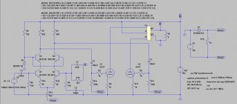
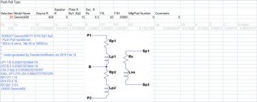
So, going back to topic, i found this transformer modeling tool by fellow diyaudio member Robert Maclean and inserted the attached values for a 600:8 OPT. Made some changes, use the transformer model and i end up with attached schematic.
Based on the stability suggestion, i chose these values:
1. OPT cutoff at 50Hz (in reality, how does one make OPT cutoff at 50Hz? adjusting the primary inductance so i end up with Xc= Rs/100 at 50Hz?)
2. C4-R12 cutoff at 7.2Hz
3. C2-R9 cutoff at 3.4Hz
Will this help fend off oscillation? I also did the AC analysis and end up with the attached result.
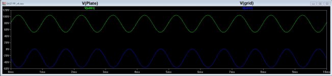
One problem: i get the 50V swing from the front end, but the plate swing is also about the same value which means the amplification from my 6AS7 is only 1x. Is this a model problem? Bypassing the cathode resistors did not help much.
So, going back to topic, i found this transformer modeling tool by fellow diyaudio member Robert Maclean and inserted the attached values for a 600:8 OPT. Made some changes, use the transformer model and i end up with attached schematic.
Based on the stability suggestion, i chose these values:
1. OPT cutoff at 50Hz (in reality, how does one make OPT cutoff at 50Hz? adjusting the primary inductance so i end up with Xc= Rs/100 at 50Hz?)
2. C4-R12 cutoff at 7.2Hz
3. C2-R9 cutoff at 3.4Hz
Will this help fend off oscillation? I also did the AC analysis and end up with the attached result.
One problem: i get the 50V swing from the front end, but the plate swing is also about the same value which means the amplification from my 6AS7 is only 1x. Is this a model problem? Bypassing the cathode resistors did not help much.
Attachments
Last edited:
1. Output transformer cutoff:
Clearly, the output trans primary reactance must equate to the reflected load impedance at the cut off frequncy. For a 90 V HT, you'll get an anode swing of around 120 V pp. That's 40 V RMS. The reflected load impedance should be about 40^2/(12/2) ie ~270 ohms. Say 300 ohm, this isn't a precision calculation. So, the primary reactance on one side must equal or exceed Z/(2.pi.f) ie 300/(2.pi.50) = 1 H.
That directly answers you question. However, human hearing is good down to 50 Hz, and much energy in music goes down to 50 Hz. And for stability C-R cutoffs in the circuit must all be well below or well above this frequency. If you choose well above, then you'll still have weak bass. If you choose well below, you'll get more distortion. So the transformer needs to cut off below 50 Hz. 20 Hz is better. Many engineers would go lower than that unless they are budget constrained.
Your choice of 50 Hz transformer cutoff, 7.2 Hz with C4-R12, and 3.4 HZ at C2-R9 shoukld be stable, but it's doing things the wrong way round. Make the the grid coupling (C4-R12, C5-R13) the controlling, ie highest cut-off, and make the transformer and C2-R9 lower frequencies. Otherwise the output transofmer will get excursions at and below its cut-off and core non-linearity will result in distortion.
Why do you want to use such an unusually low HT voltage?
No, you will not find a low ra triode with a high amplification. A tube factory engineer has two ways to get low ra in a triode:-
a) choose a very long structure so that the cathode emission area is large. That makes for avery expensive tube to make.
b) reduce the anode/grid spacing, which reduces amplification.
Tubes like the 6AS7 wwere made for use as series-pass in regulated power supplies in profesional equipment. In these applications, a low ra is needed but amplification doesn't matter.
If you want voltage gain at a low HT voltage, choose a pentode designed for television line output service eg 6CM6, 6DQ6, etc.
2. Swing on plate similar to swing on grid:-
The 6AS7 has an amplification of 2, according to datasheets, but that is at an anode voltage of 135 V. The problem could be a result of a number of small factors and issues with the SPICE model. Obtain the anode curves for 6AS7 and work it out graphhically. Doing it graphically takes seconds - far less time than messing about with SPICE. It will helkp you understand it better, too.
A beginer messing about with SPICE is like a student doctor using the latest DaVinci robot to do an advanced keyhole operation without first having assisted in a straightforward injury sew-up. The patient would probably die, and he'd have no idea why! Similary, SPICE is not helping you much - nowhere near as much as getting out your calculator and some scrap paper, and using that computer built in between your ears.
3. Use of mains transformers as output:-
To reflect 8 ohms speaker impedance back to 600 ohms anode-to-anode at primary, you'll need a turns ratio of 8.66. So, for a 115V volt primary you will need a 12 V secondary. If you take a typical 12VA mains transformer, the magnetising current is around 60 mA. So, primary inductive reactance equals 115/0.06 ie 1900 ohms. Thus primary inductance is 1900/(2.pi.50) ie 6 henries.
So yes, this is indeed sub-optimal. But it isn't the main problem. The primary resistance (cold) of a 12 VA mains transformer will be around 150 to 200 ohms. So you are goind to loose around half your power output in transformer joule losses.
As I see it, you have 5 choices:-
1) Accept that your amplifier is going to give weak output;
2) Use a more sensible HT voltage
3) Use a custom transformer.
4) Use a very large transformer, say 100 VA.
5) Use transistors throughout, and no tubes - no need for a transformer then.
Last edited:
When i started this, i was ready for something that will output something less than 2 Watts.. so i already accepted option 1
This is for desktop amp coupled to near-field speakers so i don't need tens of Watts. If i end up with something around 6-8 Watts@8 ohms, i'd be smiling wide.
My "OPT" is 230v to 24v toroidal mains transformer so i got the ratio right. Sadly, it's rated for only 7VA.
I will also be using a TV cathode ray tube SMPS that has 85v and 115v output. I chose the 85v as i thought 115v is too much for the SS front end. This answers the why i chose such low B+.
Knowing this, is there anything else you can tell me? Expected power output, perhaps?
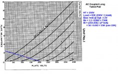
I think i know how to draw loadlines for Class AB output stage. Attached is one attempt when i was on the design stage of a 6FD7 PP bass guitar amp and the amp is working now. Let's see if i can do the same for this 6AS7 PP amp.
This is for desktop amp coupled to near-field speakers so i don't need tens of Watts. If i end up with something around 6-8 Watts@8 ohms, i'd be smiling wide.
My "OPT" is 230v to 24v toroidal mains transformer so i got the ratio right. Sadly, it's rated for only 7VA.
I will also be using a TV cathode ray tube SMPS that has 85v and 115v output. I chose the 85v as i thought 115v is too much for the SS front end. This answers the why i chose such low B+.
Knowing this, is there anything else you can tell me? Expected power output, perhaps?
I think i know how to draw loadlines for Class AB output stage. Attached is one attempt when i was on the design stage of a 6FD7 PP bass guitar amp and the amp is working now. Let's see if i can do the same for this 6AS7 PP amp.
Attachments
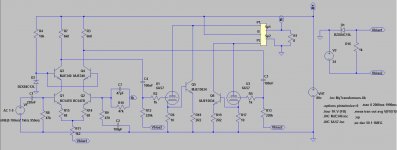
I have some space left on the PCB i designed and was wondering if there is anything i can add to the attached schematic that would improve the performance?
A simple resistor was deliberately chosen over CCS on the LTP's tail, so please don't suggest this.
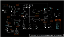
An interesting project for hybrid amplifier with tube 6N13S (6080,6AS7) that works perfectly, has been completed and practical.
The amplifier is very stable and the performance is excellent. If you would double end pipes, power will double, but have a different output transformer and power supply but scaled.
It's just a suggestion!
Input signal is 7,7Veff, so you need a preamplifier adapted.
Observed lack NFB!
If I upset I apologize for action!
Attachments
Last edited:
Then a significant improvemnt is available at almost no cost & effort:-
Use the 115V rail, not the 85V rail. That will about double the power output.
The MJE340 has a Vceo rating of 300V. There is no problem there!
Are you sure you need only 2 watts? I had my workbeanch PC sound card playing thru car radio speakers installed in the bench backboard (ie betwen the bench worktop and the test gear shelf above. Car radio speakers are quite efficient compared to hi-fi speakers. The sound card has an output of 4 watts per channel.
This proved adequate for listening to music in the background, playing quietly while I work. But if I heard a tune I really liked and turned it up to hear it clearly, but not loud, bass overloaded the sound card. So I built a 20 watt per channel amp and interposed it between the sound card and the speakers. Checking with a CRO showed it is indeed delivering 20 W before clipping, but on music turned up enough to hear clearly but not loud, some CD's caused occaisonal clipping. And while I am in my 70's, I'm not deaf - my ears have been checked.
You do the graphical calcs for 6AS7 and a HT of 115V, and let us know what you come up with. I'm too lazy, and if I do it for you, its like SPICE, you'll learn nothing.
A 230V/24V transfomer will have about 4 times the winding resistance of a 115/12V transfomer for the same VA rating. So a 230 V 7VA transformer is not a good choice at all. Almost all the audio power will dissappear in the transfomer.
Ever thought of recycling an old power transformer, and winding your own transformer on the old core? The design clacs aren't that difficult, but you'll need some ingenuity in winding without a coil winder.
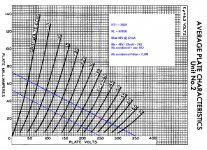
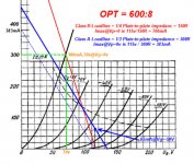
So.. here's the graph calc for 600:8 OPT at HT 115V. Sorry for the blurry pic. Extrapolating up to 800mA of current cost me laptop screen estate so i had to resize the pic.
Anyway, Looks scary! The class B part mostly resides above Pmax.
With my current PS, i can only get around -50v of fixed bias. With that value of Vg, idle current is at 65mA.
At Vg = 0v, peak current is 300mA @ Vp = 70v. So, output power would be: (115-70)*300mA / 2 = 6.75W. Assuming i lost half of it on the OPT, i get around 3.5W at the speakers. Not bad.
Now the challenge is to get the front end to swing 100Vpp with HT of 115v while considering sufficient bias current to cope with the tube's Miller capacitance, the transistor's power dissipation and getting enough gain for full power from a typical line level (say 2Vpp).
Did i make any mistake? If not, using HT of 85V looks more interesting as i am keeping the tube cooler. That, or higher impedance OPT. Also, less swing required from the front-end.
edit: i'm gonna say no to rewinding old transformer right now.
Attachments
Last edited:
For the Class A case, from your graph it appears that for reasonable linearity the most negative grid voltage is about -60V. So the bias point should be half this ie -30V at which 170 mA will flow per tube. This is a tube dissipation of 19.5 watts. Both current and dissipation are well outside tube maximum ratings (125 mA, 13 watts per side).
So, bias for 13/115 = 113 mA - this requires a grid bias of -45 V. So the useable grid swing is from -60 to -30V. The load line needs to be shifted upwards to pass thru 113 mA at 115V. At this bias, the grid curves show the anode current swing will be about 60 mA to 160 mA. The anode voltage swing will be about 30 V pk to pk.
Thus the grid voltage swing is indeed about the same as the anode voltage swing - there is no voltage gain. An anode swing of 30V and 100 mA is an audio output of 10.6 V RMS and 35.4 mA. So audio output at the onset of significant distortion is 10.6 x .0354 per tube ie 0.75 Watts total. Negative feedback will push this out, perhaps to 1 watt.
If you use a 230 V 7VA transformer, copper joule losses will bring it down to roughly 0.25 to 0.3 watts.
With no voltage gain in the tube, there is mimimal miller effect. 6AS7 grid-plate capacitance is 10.5 pF, so the HF cutoff will be at 1/(2.pi.2.10.5x10^-6.12x10^3) ie 610 kHz. Clearly getting the transistors to cope with miller effect is a complete non-issue.
Neither is getting enough driver gain.
Your big issues here are using an unsuitable tube combined with too low a HT voltage compounded by a very unsuitable output transformer.
Last edited:
")
- Status
- This old topic is closed. If you want to reopen this topic, contact a moderator using the "Report Post" button.
- Home
- Amplifiers
- Tubes / Valves
- Improvement Suggestion Wanted: 6AS7 Hybrid PP Amp