Sorry if this is a dumb question.
I'm putting together a design for DC for 845 heaters (10V @ 3.25A). Ideally I'd like to just go for a simple bridge rectifier and then CLC filter, I've sim'd it with PSUD2, and it's all fine and good, I know what I'd need for component values and ratings.. The problem is that I'm assuming the heater won't be drawing 3.25A instantly so there will be a brief period of time when the voltage won't drop over the choke so there will be significantly higher than 10V on the heater/cathode.
I've been trying to find some info on how long this full current draw will happen, or how long I'll have a high voltage on the heater/cathode...
Does anyone have some experience with this? Is it safe if it's just for a short period of time?
If any, the current draw will be more than 3.25A during cold starts, not less. Heaters are PTC resistors: increases in resistance with temperature. Anyway, no need to worry.
+1
When the 845 is cold, the filament is a near short-circuit (try measuring it). The voltage will not be high when you apply the supply voltage - it will be low. This is because the high turn-ON current drawn by the cold filament.
If you do not limit the turn-ON current, it can reach a very high value. However, they do warm up quickly.
Sadly, a plain rectified dc with CLC filter does not do very well in keeping the rectifier pulses (forward pulses and reverse recovery) out of the filament - and since the filament is a conductor which also carries the cathode current (the music signal), the sound is degraded.
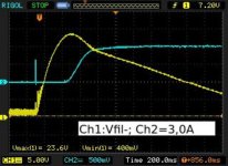
The attached picture shows the startup time of a GM70 (20V 3.0A). This filament is being heated with a current-driven regulator, for better sound, and lower inrush current.
The BLUE is the rising of the current (limited to 3.0A), and the YELLOW is the falling voltage across the control element. In this case, everything is stable within about 1 second.
If you do not limit the turn-ON current, it can reach a very high value. However, they do warm up quickly.
Sadly, a plain rectified dc with CLC filter does not do very well in keeping the rectifier pulses (forward pulses and reverse recovery) out of the filament - and since the filament is a conductor which also carries the cathode current (the music signal), the sound is degraded.
The attached picture shows the startup time of a GM70 (20V 3.0A). This filament is being heated with a current-driven regulator, for better sound, and lower inrush current.
The BLUE is the rising of the current (limited to 3.0A), and the YELLOW is the falling voltage across the control element. In this case, everything is stable within about 1 second.
Attachments
When the 845 is cold, the filament is a near short-circuit (try measuring it). The voltage will not be high when you apply the supply voltage - it will be low. This is because the high turn-ON current drawn by the cold filament.
If you do not limit the turn-ON current, it can reach a very high value. However, they do warm up quickly.
Sadly, a plain rectified dc with CLC filter does not do very well in keeping the rectifier pulses (forward pulses and reverse recovery) out of the filament - and since the filament is a conductor which also carries the cathode current (the music signal), the sound is degraded.
The attached picture shows the startup time of a GM70 (20V 3.0A). This filament is being heated with a current-driven regulator, for better sound, and lower inrush current.
The BLUE is the rising of the current (limited to 3.0A), and the YELLOW is the falling voltage across the control element. In this case, everything is stable within about 1 second.
Thanks guys! This is some great information.
I actually have some 20V 5A transformers as well as 22mF 25V caps, so I had thought about doing a near choke input filter with maybe a CLCRCRC filter.. Fine tuning the voltage with those last resistors values for exactly 10V. Are these pulses still an issue with low ripple current and a lot of filtering?
Also, with no current draw this power supply would be putting out around 26V... So hopefully for the sake of the capacitors and heater of the 845's they wouldn't ever see a voltage this high with instant current draw.. That's a safe assumption even with much much higher than 10V with no current draw?
Here's a PSUD2 sim I just did with the components I have.. around 1mV of voltage ripple

Fairly low ripple current as well:
IT1:

IC1:

IC2:

Last edited:
Also, with no current draw this power supply would be putting out around 26V... So hopefully for the sake of the capacitors and heater of the 845's they wouldn't ever see a voltage this high with instant current draw.. That's a safe assumption even with much much higher than 10V with no current draw?
The only time the heater voltage can be higher than you have tweaked it for, is when the heaters are not there at all! Think Ohm's law.
The only time the heater voltage can be higher than you have tweaked it for, is when the heaters are not there at all! Think Ohm's law.
It's a good idea to allow for this condition, of course.
The filament may break open-circuit one day, or one may apply power with the valve out of the socket.
I have a question about the diode bridge in a configuration like I've shown in the screenshots.. I would be using Vishay MBR1045 schottky diodes, I was thinking I would likely have to use heatsinks on the diodes.. Is that right?
What kind of heatsinks I would need to use, given that there would be 3.25A of current draw?
Here is the datasheet for the diodes http://www.mouser.com/ds/2/427/mbrfb1035-104135.pdf
Would someone be able to lend a hand in helping me determine what kind of heatsinks I should use?
What kind of heatsinks I would need to use, given that there would be 3.25A of current draw?
Here is the datasheet for the diodes http://www.mouser.com/ds/2/427/mbrfb1035-104135.pdf
Would someone be able to lend a hand in helping me determine what kind of heatsinks I should use?
The Vishay data is not very helpful, but the ST data for the similar STPS1045 shows some power dissipation data.
For 3.5A dc (top-end of 845 current), the expected rms current is about 6.3A rms.
Each diode (in a bridge) sees half of these values.
According to ST, the power burn is:
0.42 x If(av) + 0.015If^2(rms)
= 0.735 + 0.59 W
= ~1.3W
TO-220 packages can usually manage a burn of 2W each, but the temperature may get uncomfortable, so a little heat-sink will help.
The total burn is about 5.3W, so a 10 deg. C/W heat-sink will keep the rise to 50 deg. C, or use a piece of Alu, 3-5mm thick, 200mm x 200mm (etc).
Attach the diodes with insulating washers, or use TO220FP packaged diodes.
I just noticed that you have choke-input filter, and only 2.3A rms.
If it is really this low, a heat-sink may not be needed. If you have a thermocouple, try it unheat-sinked, measuring from cold, and ensure the temperature is suitable for the inside of the amp (maybe 80 deg. C)
If it is really this low, a heat-sink may not be needed. If you have a thermocouple, try it unheat-sinked, measuring from cold, and ensure the temperature is suitable for the inside of the amp (maybe 80 deg. C)
Indeed. The forward voltage is around 0.4V at 3A, so the dissipation is likely to be under 1.2W. A TO-220 package can normally handle 1W without a heatsink, so you should be OK. If not, even a postage-stamp sized piece of aluminium plate bolted to each diode would be enough.
Maybe something like this would be suitable? V6560W Assmann WSW Components | AE10901-ND | DigiKey
Even smaller, if you mount one on each diode.
Oh, I was looking at the 10 degree C / W rating.. But I guess that was based on higher current draw than choke load..
Maybe something like this? 507302B00000G Aavid Thermalloy | HS115-ND | DigiKey
Perfect
Should I even worry about electrically isolating the diodes from the heatsinks?.. The heatsinks are so small I'm not really worried about anything coming in contact with them.. But I do have TO-220 mica insulators, and I was looking at these shoulder washers http://www.digikey.ca/scripts/DkSea...=635598548379412284&CSRT=11145698553390996302 which I believe are the right size and shoulder length for the heatsink thickness plus the thickness of the diode itself.
But I suppose thermal transfer would be reduced using the mica insulators..
At the 1W level, the difference made by the Micas is near-negligible.
I would insulate - imagine the mess if you drop a screwdriver in there!
Alternatively, the STPS1045 FP version is better still for insulation purposes, and the thermal properties will be more than adequate.
I would insulate - imagine the mess if you drop a screwdriver in there!
Alternatively, the STPS1045 FP version is better still for insulation purposes, and the thermal properties will be more than adequate.
At the 1W level, the difference made by the Micas is near-negligible.
I would insulate - imagine the mess if you drop a screwdriver in there!
Alternatively, the STPS1045 FP version is better still for insulation purposes, and the thermal properties will be more than adequate.
I'm trying to see what the difference is with the FP version, is it that it has a built in isolation? So I could just bolt it directly to the heatsink without there being any electrical connectivity?
Are these the right guys? http://www.digikey.ca/product-detail/en/MBRF1045-E3/45/MBRF1045-E3/45GI-ND/2153374
Last edited:
- Status
- This old topic is closed. If you want to reopen this topic, contact a moderator using the "Report Post" button.
- Home
- Amplifiers
- Tubes / Valves
- DHT heater current draw - how fast?