Thanks crismont43 it was the capacitor causing the fireworks in the rectifier.
I have corrected it but now when I switch on I get a loud, very loud, mains hum and no signal. I suspect the 220 uF cap is now kaput so I'll order a replacement and see how it goes.
I'll get a larger capacity/better quality one as that seems to be an obvious place for improvement.
I have corrected it but now when I switch on I get a loud, very loud, mains hum and no signal. I suspect the 220 uF cap is now kaput so I'll order a replacement and see how it goes.
I'll get a larger capacity/better quality one as that seems to be an obvious place for improvement.
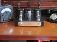
OK the amp is running fine now. I had not connected pins 1 & 4 on the triodes. The hum is all gone now and a lovely clear sound is coming through. It's very easy to overlook that connection and thanks for pointing this out ygg-it (post 53).
I'm now enjoying some music while the valves settle down.
Below is a picture of the amp along with my state-of-the-art measuring equipment. ;-)
I'll now set about building a second amplifier the same; only with paper-in-oil caps etc as suggested in the thread. If that works well I'll do the same mods to this first amp.Then I will use them for treble and midrange in a 3-way active configuration with my old transistor amplifier driving the bass.
Attachments
I have just build my Boyuu A9 and wanted to test it in stages. With no valves fitted I thought I would measure the AC voltages on the mains transformer first. Starting with the 315-0-315 taps I connected a meter between the Ov and 315V on the AC 700V range. I was surprised to get 180V with the amplifiers mains switch switched OFF. I did not switch the mains switch on for fear of incorrect wiring but I am sure I have wired it up correctly.
Am I getting this voltage because I have a 0.1uF/275V capacitor across the mains switch which is passing AC as this is in circuit when the switch is in the off position?
This is the first product that I have built where only the Live is switched (all other products I have built switch both the Live and Neutral).
I would appreciate some help before I proceed with this.
Thanks in advance - Nigel
Updated message - I removed the 0.1uF capacitor (C304) from across the mains switch and plugged it into the mains with the amplifiers on/off switch in the OFF position and the output from the 0V - 315V taps was 0V.
I then refitted this capacitor across the mains switch and plugged it back in. Now I get 180V on the 0V - 315V tap with the amplifiers on/off switch switched OFF.
When I switch it ON the voltage rises to 330V, when I switch it off it drops to 180V.
So this capacitor is causing this voltage to be present when fitted and switched OFF.
I am wondering if this voltage will drop when loaded by the rectifier valve (which is at present not fitted)
I am in the UK (so 240V mains). The amplifier was supplied with a 220V mains lead so assume that the mains transformer was intended for the European market.
The output voltages I am getting from the 315 - 0 - 315 taps is 330 - 0 - 330, 5.26V for the rectifier, 6.63V for the triodes and 6.63V for the pentodes.
To compensate for the increase of what will be coming out of the rectifier valve I have increased the value of R301 from 39R to 66R by adding a 27R 25W resistor in series with the 39R.
Any comments on the above would be appreciated.
Thanks Nigel
nice to see that there are still some people working on that little thing ") I also got hands on a Boyuu.
I also got hands on a Boyuu.
Got it, ready build, for less than the kit, so... First thing was to replace the mains switch. Next will be to change the cap across it by something which is aproved X1 or X2.
I also replaced C302 by a biger one i had arround. 560µF if i remember right. Then the cover did not fit any more, so i lifted it up by putting a 2mm rubber plate between chassis and bottom plate. Bolts are still long enough.
So what's the next thing? One input is enough for me, so the second and the switch will have to go.
The volume pot is also on the list. The EIZZ switch i have did not fit Maybe i will try to mount it somewhere near the back, or use smaller Alps.
And of course all the other mods done and described here
I am not an electrician so i have 2 questions. First, can i use a pot instead of the two 100Ohm resistors grounding the heater voltage? Maybe that could be used to minimize hum (read about this somewhere)
Second, here i can read that the output transformers are the bottleneck of this little amp. Any suggestion what could be used instead of the original ones?
Thanks Joachim
I also got hands on a Boyuu.Got it, ready build, for less than the kit, so... First thing was to replace the mains switch. Next will be to change the cap across it by something which is aproved X1 or X2.
I also replaced C302 by a biger one i had arround. 560µF if i remember right. Then the cover did not fit any more, so i lifted it up by putting a 2mm rubber plate between chassis and bottom plate. Bolts are still long enough.
So what's the next thing? One input is enough for me, so the second and the switch will have to go.
The volume pot is also on the list. The EIZZ switch i have did not fit
Maybe i will try to mount it somewhere near the back, or use smaller Alps.And of course all the other mods done and described here
I am not an electrician so i have 2 questions. First, can i use a pot instead of the two 100Ohm resistors grounding the heater voltage? Maybe that could be used to minimize hum (read about this somewhere)
Second, here i can read that the output transformers are the bottleneck of this little amp. Any suggestion what could be used instead of the original ones?
Thanks Joachim
Yes, you can use 100R resistors.
hmm i would not use this resistors but replace them by a pot
Even better, bias the heaters up to 30 ~ 40 VDC above ground. A 10uF capacitor will make your heaters AC "grounded". You should see a drastic drop in AC hum yb doing this.
No skills for that
I'm always wondering why the tubes are not always heatet by DC.
To dificult, to complex, to expensive in those days?
Maybe i will try to use a rectifier and a voltage regualter some day.
Or not
regards Joachim
Hi Joachim,
Sure, use a pot. If you bias the heaters up, the pot won't accomplish much. These days I just use fixed resistors.
What might make sense is to run only tubes working with low level signals off DC heaters. The rest of the tubes will be happy with an AC heater biased up.
-Chris
Sure, use a pot. If you bias the heaters up, the pot won't accomplish much. These days I just use fixed resistors.
Mostly because of the extra heat generated, and the likelihood of generating noise that will end up on the other windings if normally rectified. A 60 Hz signal doesn't couple well with normal capacitance between the cathode and heater. Bias it and that is reduced. If the cathode happens to be grounded (or grounded through a capacitor for AC), you haven't a lot to worry about.I'm always wondering why the tubes are not always heatet by DC.
What might make sense is to run only tubes working with low level signals off DC heaters. The rest of the tubes will be happy with an AC heater biased up.
-Chris
Sure, use a pot.
i will do
What might make sense is to run only tubes working with low level signals off DC heaters.
There i have seen that.
Thanks for enlighten me
regards Joachim
Close the power switch, and then open the switch; you are driving the primary of a power transformer with a 0.1uF capacitor (about 26k Ohms of capacitive reactance). Then if you have all the secondaries unloaded:
When the switch is closed, there will be current through the primary. When you open the switch, the inductive kick may cause the 0.1 uF capacitor to short. Some of these caps are 'self healing' or at least partially so (in that case it may be quite a bit less than 26k Ohms).
What is your power line voltage? What is the voltage rating of the 0.1uF cap? The voltage rating needs to be many times the line voltage, Especially if you close and open the switch when all the secondary windings are unloaded (not a good idea for the cap, and not a good idea for the power transformer). And Tube Rectifiers are not a load until they warm up. So the only loads at the beginning are filaments.
Take a new 0.1 uF, and connect it to the transformer primary without closing and then opening the switch. It should not have 180V on the B+ secondary. But it may do so if after that you close then open the power switch because of inductive kick, so do not do that without filaments connected to their respective secondaries.
Last edited:
The Boyu Hum
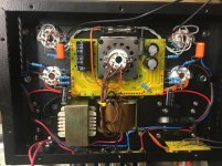
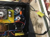
So with the guidance of this forum I put one of theses together without fire flame but yes the HUM. Thank you to the guys who posted a lot of the answers it took the black and blue marks away from my head, but that dam 60 Hz HUM. I will try this week to do the mods that are said to correct it. I have to go raid Vintage Hi-Fi of Pittsburgh’s parts bin to get what I need, he has all the needed parts sitting on the shelf. Set 2 pics of how I put it together. I took the power switch out and the volume just to see if it had anything to do with the HUM.
It hums just like a 75kva transformer and I have the simple answer wht. It just doesn’t know the words.
Thanks Natoe
Attachments
natoe,
Are you saying that the transformer Audibly Hums, like a transformer on the power pole outside you house?
If the amplifier works properly, with proper voltage and current draw, then it sounds like you have either a poor quality transformer, or one that was dropped which loosened the laminations.
Or, the same could be said for the B+ choke if it was dropped and disturbed the laminations.
Or are you saying that there is lots of hum in your speakers?
What kind of cap are you going to put on the 120V power line? What kind of connection.
You can not stop hum that way. But put a cap Across a 120V power line, and the only thing that may happen is an explosion or fire.
The 0.1uF cap across the power switch does not increase, nor does it decrease hum when the switch is closed.
Last edited:
Evening all. After 8 weeks of trying to get mine working, blowing up transformers and lots of swearing, he’s finally working and sounding lush. Can’t wait to hear the results once the valves are broken in.
Had the same hum problem. Fitted the 3.3k resistors to the input lines and 50 ohm resistors to the 6v heaters on the input valves tonight, and it’s practically silent. Thanks to all on here who have helped and advised
Had the same hum problem. Fitted the 3.3k resistors to the input lines and 50 ohm resistors to the 6v heaters on the input valves tonight, and it’s practically silent. Thanks to all on here who have helped and advised
- Home
- Amplifiers
- Tubes / Valves
- Boyuu EL34 A9 Tube Amp