Hi again. I've taken a series of very high-res pics which I've put here:
Index of /valves
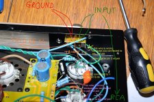
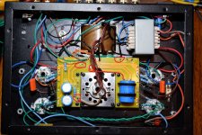
You can see a lot of detail in here. Please forgive my bad soldering. Note the brown earth from the input board - I think that may be incorrect for starters but let me know if anything obvious stands out.
Index of /valves
You can see a lot of detail in here. Please forgive my bad soldering. Note the brown earth from the input board - I think that may be incorrect for starters but let me know if anything obvious stands out.
Even with your hi-rez pics, it's a bit difficult to figure out 'what's connected to what' as the PCB has traces on both sides (?). You probably have a better chance with the amp in front of you.
If it were my project, I'd print the schematic and use a coloured pen or highlighter marker to trace each connection. Having a bit of a 'system' works for me...start with the power transformer, trace the heater connections, then the connections to/from the rectifier tube through the B+ supply and out to the tubes. Inputs from jacks to volume controls to preamp tubes. etc..you get the idea.
Assuming the input jacks are insulated from the chassis - yes, you need a 'ground' connection from the inputs to the amp ground bus.
About the volume controls - yes, you need a connection from the 'bottom ends' of the pots to the ground bus trace on the PCB.
Try to route those low-level signal leads away from AC (heater wires). Using stranded wire makes it a bit more difficult to keep things in place - you can tape them in place if necessary.
I see you have a meter. Do you have any other test 'stuff' like test leads with grippers, alligator clips, etc. ? I don't like hand-holding test leads to test voltages; I prefer to clip them on and then power up - slower but no chance of a slip causing excitement. Even being able to clip the ground lead, hand-holding the 'red', helps.
Since you don't have 'spaghetti' aka sleeving on any of the leads, double check that you don't have any unwanted contacts.
Be sure to have dummy load or cheap disposable speakers connected during testing...though this is subject to debate, I do it.
Grazie ygg-it. Can you explain that wiring to me then? The other two pins are common and I'd have thought that it's those (on the far left in the picture) that would be earthed. Currently the input is on the pins marked with the white "I" on the board and the outputs on the far right. I want to get this exactly right before I rewire them. Thanks for your time.
My advice would be to focus on the actual pot connections, not the PCB, if you are trying to match your wiring to the schematic. If necessary, take the knob off and unbolt the pot & PCB from the faceplate, and figure out what is connected, to what.
At that point, why not use your ohm-meter and figure out how the pots work? Which way of connecting will give you a 'straight through' (low resistance) connection between the input from the CD player (?) and the wiper which is connected to the tube grid, when the knob is turned fully CW?
I wouldn't assume that my idea of 'I'nput is the same as the person who made the PCB. (It could be 'wire to 'I'nput of first tube ??)
Same advice on the power supply PCB.
Schematic
Coloured marker
Go through the whole amp.
Then, voltage checks.
Last edited:
I've checked the pot with the ohmmeter and it appears the wiper is the centre pin, i.e. the current input connection, and the output is the currently connected output pin. The resistance varies correctly to practically nothing where the wiper shorts to the output pin. The unconnected pins, which on the board are connected and common, must be the earth connection which I need to complete. I'll give that a go.
Well that didn't change anything. I'm certain that all the components and pins are correctly connected. The valve heaters appear to be correct. I think the problem lies in the output transformer connections which I've only gone on the photographs of other Boyuu amps for the colours and positions. I've no idea how to work out if these are correct or not so I think I'm at the end of the road here with a heavy door stop on my hands.
To anyone reading this - think twice before buying one of these kits.
To anyone reading this - think twice before buying one of these kits.
Perhaps I misunderstood, but didn't you decide to leave the pot wipers attached to the input signal leads rather than following the schematic?I'm certain that all the components and pins are correctly connected.
That wouldn't keep the amp from working, so it's not your 'main problem', but.......
If the components are connected exactly as the schematic directs, I'm pretty sure you will have a working amplifier. If your amp isn't working, something is probably connected wrongly, or you have a damaged component.
That's checking the AC voltage across each tube heater?The valve heaters appear to be correct.
And did you check the (DC compared to ground) B+ (B1,B2, etc) voltages and the DC voltages on the plates and cathodes of the tubes?
Posting a list of those voltages would help folks here who want to help you.
I think the problem lies in the output transformer connections which I've only gone on the photographs of other Boyuu amps for the colours and positions. I've no idea how to work out if these are correct or not .
??
Disconnect the OT and use your meter to figure out the windings. It's not difficult- you just need to use the ohmmeter to figure out which leads are connected to each winding, and then figure out the order. There are plenty of descriptions on how to do that. Search. Or, just ask. Then, following the schematic (not a photograph), re-connect the OT.
Deja vu:
Also, checking the output transformer windings with an ohmmeter and sorting out the leads is a good idea - labelling the leads or making clear notes in your 'project notebook' would be my recommendation.
If you don't enjoy problem-solving, it can be frustrating. Perhaps think of this not as an amp, but as an 'electronics learning kit', and enjoy the experience as much as possible?
Last edited:
Grazie ygg-it. Can you explain that wiring to me then? The other two pins are common and I'd have thought that it's those (on the far left in the picture) that would be earthed. Currently the input is on the pins marked with the white "I" on the board and the outputs on the far right. I want to get this exactly right before I rewire them. Thanks for your time.
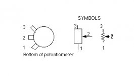
Please refer to my pic.
Attached the correct potentiometer wiring. Pin 2 of the pot must be connected to pin 4 of the triode!
So when you rotate the volume knob, the triode's grid must go or to the ground (no sound) or to RCA-input (clockwise, max sound).
Pin 1 of the pot are the ground and must be connected together.
Also you forget to connect pin1 to pin4 of the triode in both channels!
The two grids are parallel connected!! These floating grids (pin 4) should be the cause of your noise!
Attachments
Last edited:
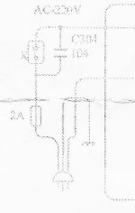
Why you miss the 2A fuse??
Please immediately insert 2A fuse (even less should be ok at initial stage) between one wire the power cord and (i.e.before) the power switch.
Do this before switch-on again your machine!
Don't exceed 2A fuse. 1.25A or 1.6A should be ok (220V*1.25A= 275W...) at this stage...
Please immediately insert 2A fuse (even less should be ok at initial stage) between one wire the power cord and (i.e.before) the power switch.
Do this before switch-on again your machine!
Don't exceed 2A fuse. 1.25A or 1.6A should be ok (220V*1.25A= 275W...) at this stage...
Attachments
Hi all. I've been running an eye check on all the connections. The only problem I can see is that I'm not running an earth from the common connection on the volume pot. And I am running an earth that I think I shouldn't be, from the common on the input board.
I don't see the ground wire connection of the pot. Please check that both pins 1 of the pot are wired to ground. Refer to my previous pic (my red connections)
If the components are connected exactly as the schematic directs, I'm pretty sure you will have a working amplifier. If your amp isn't working, something is probably connected wrongly, or you have a damaged component.
In effect the parallel grid connection in the schematic is very UNCLEAR for the majority of the users!
Myself too (but I bought the machine already wired) have to check this with a multimeter, just to be sure...
Pin 1 must be connected to pin 4. Fortunately leaving them floating should not have caused damages to the triodes. They just acted as RF antenna and mixed the input audio signal due to the fact that the parallel connection of anode and cathode are wired correctly!!
Parallel triodes work fine because they lower the noise. Unfortunately Miller capacity double, but since this kit is missing of the grid resistor, this should not lower the frequency response too much.
I would put a 2,2k-4,7k resistor from pin 2 of the pot to pin 1+4 of the triode, instead of wiring them directly.
In any case our English friend must rewire correctly the pot before trying this.
Last edited:
You are correct.
Good points.
Without ground connections on the inputs/volume control (all the way through the amp actually), nothing much can be expected. Those connections seem minor, looking at the schematic - easy to miss for a beginner, I guess ...(?)
I'm still wondering about the power supply wiring connections - are there traces under the PCB? Some voltage tests would help.
I can understand humming/buzzing/RF noise on top of the normal output (with volume control fully 'open' ). Very low volume usually means to me that it's either oscillation (that can't be heard) or lack of amplification (because of connection or power supply problem).
I bought a similar kit a few years ago and got some suggestions here for a different way of wiring, using most of the 'kit' components. It works well.
These Chinese 'kits' are nothing like the old Heathkits....it's easy to get fooled.
")
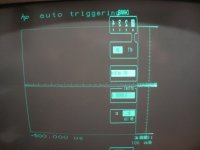
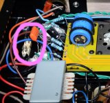
I'm still wondering about the connections to the power supply board.
There are traces underneath the board which don't show in the pictures.
I marked a few of the ?? spots on the attached pic.
If you can measure the DC voltages between ground and:
-Pin 2 or 5 of each input tube
-Pin 3 of the EL34s
-Pin 4 of the EL34s
-the + end of the large 150 uF capacitor
and post them, that would clear up some of the power supply questions in my mind.
Thanks.
Attachments
Hiya VictoriaGuy
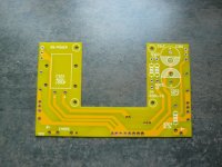
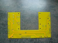
I have been reading this with interest as I have not started mine yet. Thought a couple of pics of the main power board might help with the fault finding.
From a very quick look at the schematic (and from a tube-noob's point of view) are the 2 connection points to C302 you have marked meant for connection of the o/p xfmr flying leads B1 ?
Attachments
Last edited:
- Home
- Amplifiers
- Tubes / Valves
- Boyuu EL34 A9 Tube Amp