I really miss my old tube pre amp (Audio Note M2 Signature) and wanted to get something to replace it. No way I can afford another one of those though.
So after a bit of reading around and a few fruitless web searches (mostly turning up Chinese junk) for suitable kits to build something I came across these:
Vacuum Tube Audio preamps
After some more deliberation I've settled on the SP12 and PH12 kits. They seem to get very good feedback and reviews from those that have used them. And I have found Roy very helpful indeed.
I've opted for the PCB kits only, and they are on their way to the UK. So I'll be looking for a suitable case, transformer, switches and pots etc. Shouldn't be a problem though.
Has anyone on here built these kits themselves? Any feedback? Anything to look out for on the build?
Also does anyone have any sensibly priced valve recommendations on the following? I have in the past used JAN/GE valves but these are getting increasingly difficult to find at sensible prices.
4 off 12AU7/ECC82
1 off 12x4
2 off 6922/6N11/E88CC
I intend to keep this up to date as I get on with the build. Probably with a few questions as I go.
Thanks
SJ
Should have updated this a while back!
This didn't take too long to sort out.
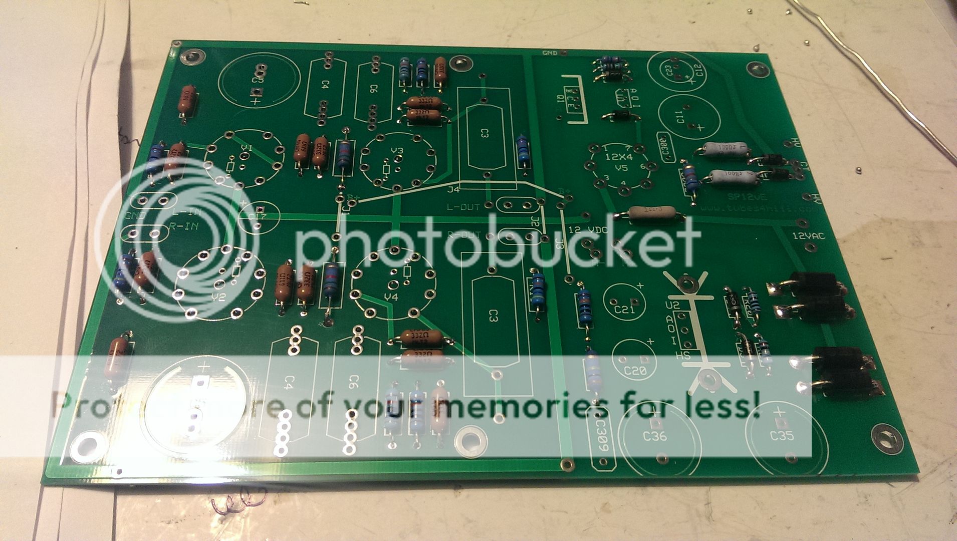
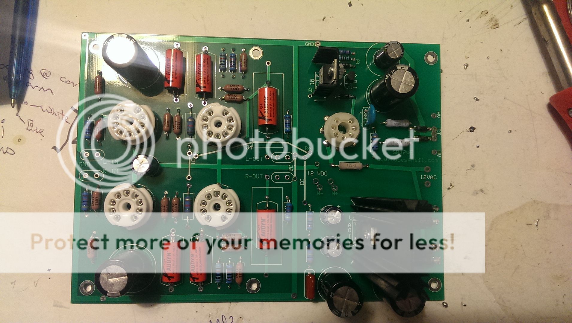
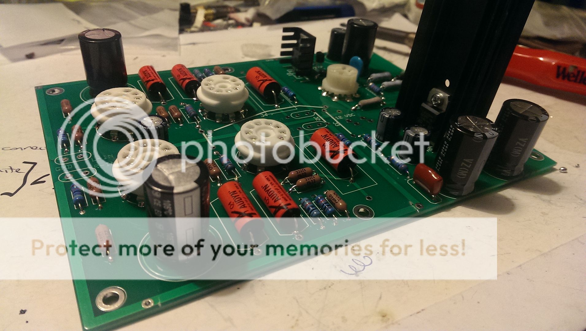
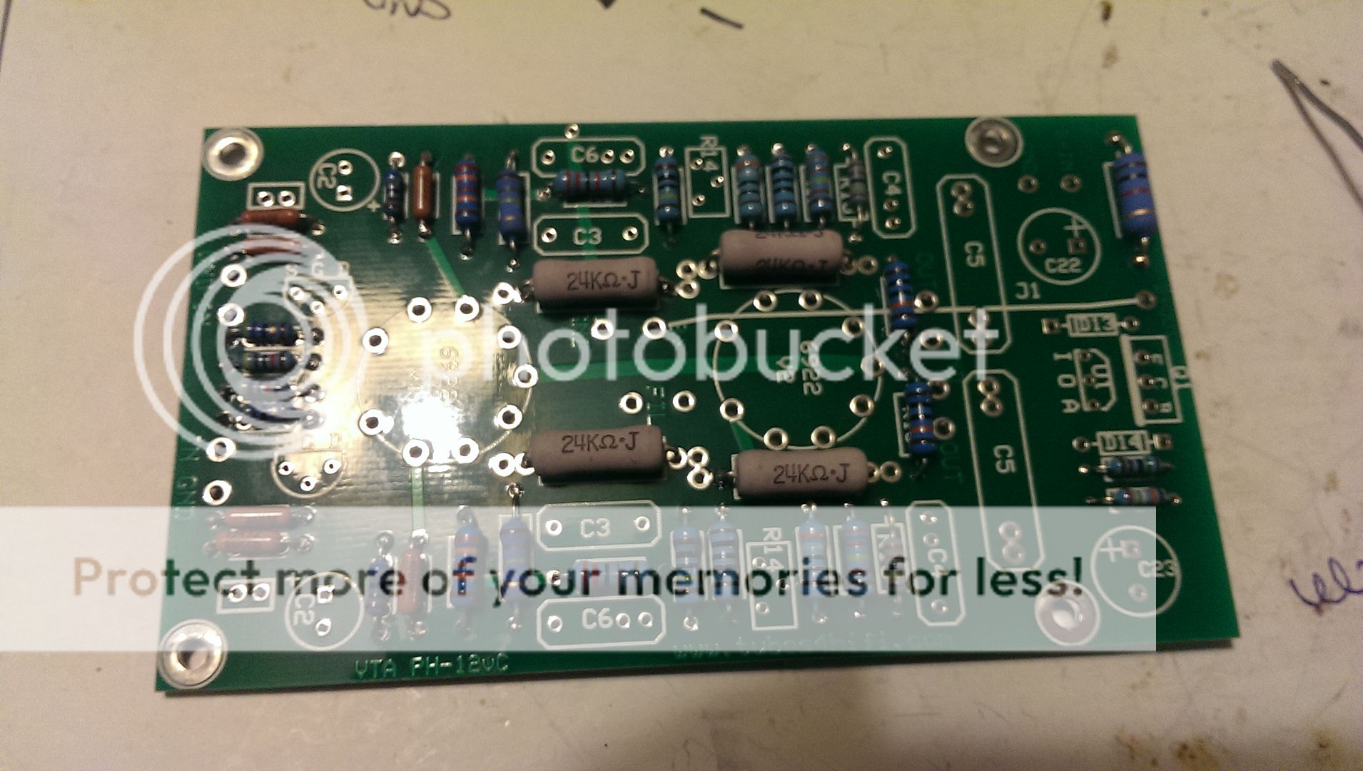
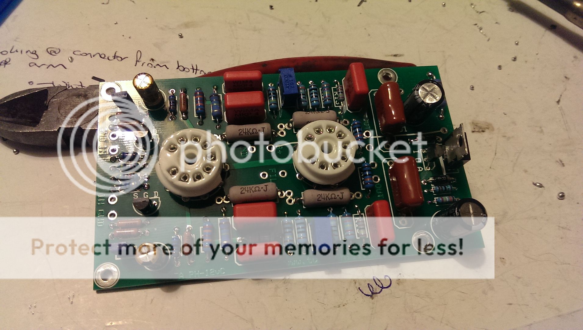
Got the PH12 built
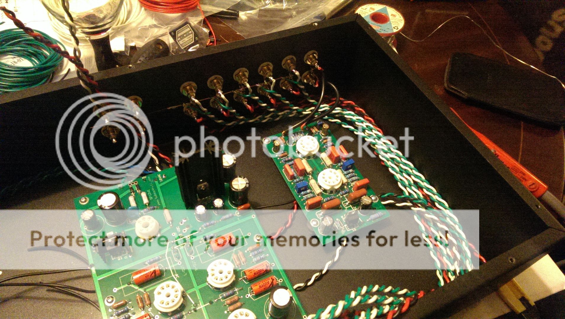
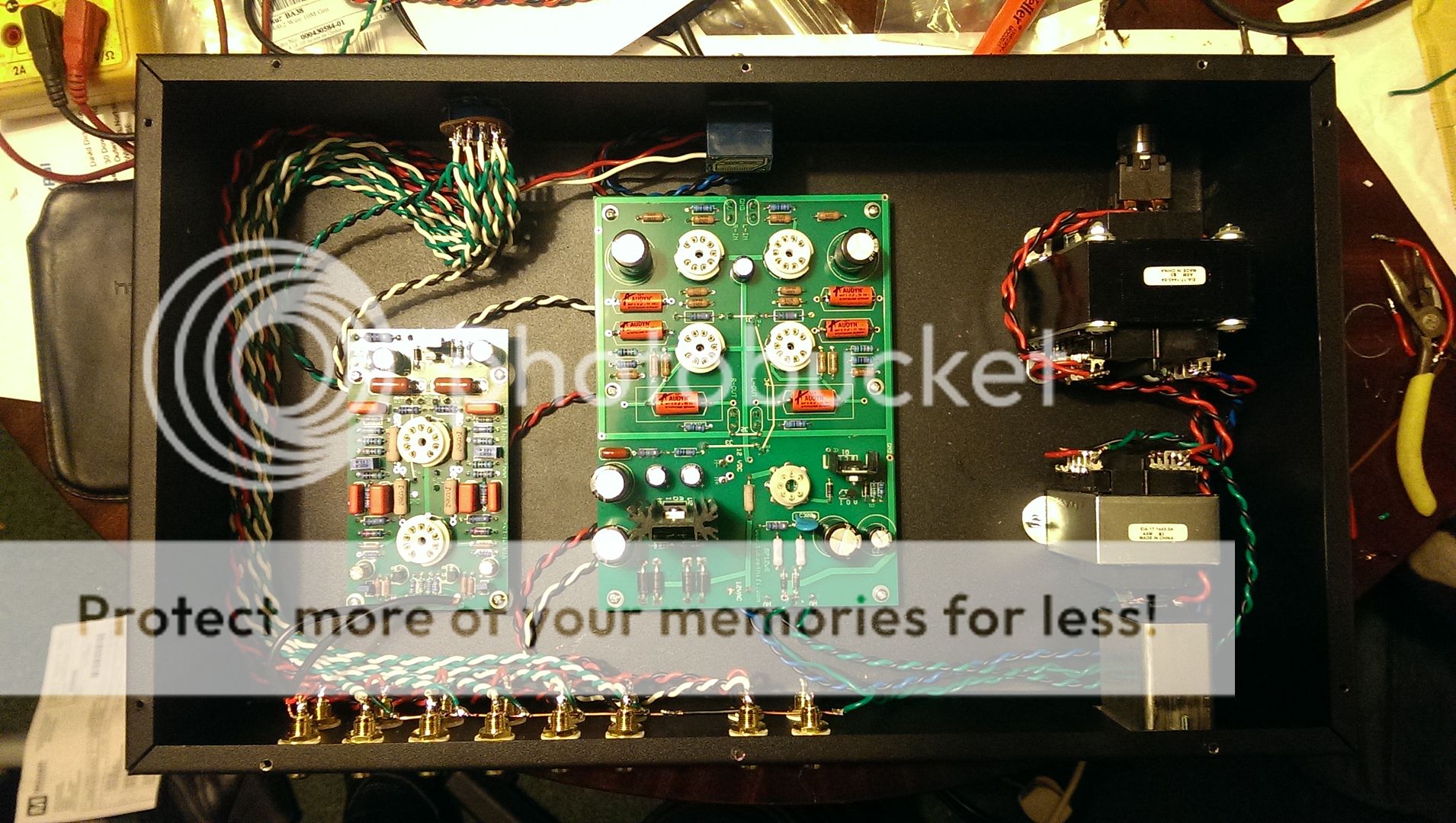
I finally got around to actually fitting everything into the case and wiring it up. Made lots of twisted pair cables in different colour combos. I need to tie all the cables up to tidy them up once I have tested everything.
A couple of quick question ref grounding on this set up, I'm wary of setting up any ground loops and want to do it right first time - I have linked all of the ground lugs on the RCA jacks (but not the phono input) with a piece of copper stripped from some household cable. All of the cables to the selector switch are grounded at the input end only.
Finished wiring it all up, and waiting for my tubes to arrive now, which should be in the next couple of days.
Connected power and checked voltages:
Getting just over 13VAC at the input of the heater circuit and 12v dc out. All good there.
Getting ~260 VAC at the input of the HV circuit. Can't check the output yet as I don't have the rectifier tube. Getting around 130VAC between ground and neutral and ground and live - at the unused CT connection at the HV input. Sound right?
Reckon I'll fit some anti-vibration pads under the transformers later this week. I'm also getting a bit of audible hum from the heater transformer so I might need to make some shielding for it. I already have a filter on the mains input.
I'm interested to note that a few people who've built these have fitted additional filtering to the PH12 power supply - so will consider this if I have any noise issues when I have it all hooked up.
This didn't take too long to sort out.
Got the PH12 built
I finally got around to actually fitting everything into the case and wiring it up. Made lots of twisted pair cables in different colour combos. I need to tie all the cables up to tidy them up once I have tested everything.
A couple of quick question ref grounding on this set up, I'm wary of setting up any ground loops and want to do it right first time - I have linked all of the ground lugs on the RCA jacks (but not the phono input) with a piece of copper stripped from some household cable. All of the cables to the selector switch are grounded at the input end only.
Finished wiring it all up, and waiting for my tubes to arrive now, which should be in the next couple of days.
Connected power and checked voltages:
Getting just over 13VAC at the input of the heater circuit and 12v dc out. All good there.
Getting ~260 VAC at the input of the HV circuit. Can't check the output yet as I don't have the rectifier tube. Getting around 130VAC between ground and neutral and ground and live - at the unused CT connection at the HV input. Sound right?
Reckon I'll fit some anti-vibration pads under the transformers later this week. I'm also getting a bit of audible hum from the heater transformer so I might need to make some shielding for it. I already have a filter on the mains input.
I'm interested to note that a few people who've built these have fitted additional filtering to the PH12 power supply - so will consider this if I have any noise issues when I have it all hooked up.
There are two ways interfering signals can leak into an audio connection: electric and magnetic induction. Coax and balanced twisted pair deal with both, although in different ways. Unbalanced twisted pair, which is what you appear to have, only stops magnetic induction so the connection is still open to any electric field sources. As this is inside a metal chassis, this means sources inside the chassis - such as power wiring.
Thanks for the explanations. I'll see what I get when I hook it up to a source and a power amp. If I have noise issues then I will consider swapping out the cabling for mic/coax cable.
Making the twisted pairs only takes a few seconds with an electric drill and a pair of pliers.")
I've wired it as recommended by others who have built the same amps. I was initially going to use mic cable for all of the inputs but then decided to follow what the other people had done.
All of the inputs are hooked up with the ground cable connected at the input end only. It's not connected at the selector switch.
Making the twisted pairs only takes a few seconds with an electric drill and a pair of pliers.
I've wired it as recommended by others who have built the same amps. I was initially going to use mic cable for all of the inputs but then decided to follow what the other people had done.
All of the inputs are hooked up with the ground cable connected at the input end only. It's not connected at the selector switch.
If I understand you correctly that probably means that the ground cable (in each twisted pair) is not actually doing anything - so you have no protection against magnetic induction either.flak monkey said:All of the inputs are hooked up with the ground cable connected at the input end only. It's not connected at the selector switch.
To minimise loop area (and so reduce magnetic induction) it is vital that the signal and return currents follow nearly the same path. Coax and twisted pair ensure this, provided that the return path is not offered an alternative or (even worse) forced to use an alternative. You seem to have sent the return current along whatever ground wiring you have from the input sockets, while the signal current goes along one half of the twisted pair. The other (grounded) half of the twisted pair does nothing if it is only connected at one end.
Note that a coax screen connected at only one end can still provide screening from electric fields, but this does not work (except to a limited extent) for twisted pair.
Thanks for the explanation. Like I said I was following the advice of previous builder of these systems. And I've not really played around with diy hi-fi stuff very much.
I was very wary of setting up any potential ground loops in the system, and sought some advice from the makers of the kit. The ground from the inputs are all linked with a copper bus bar and this then goes to the main star ground in the case, where the ground from the line stage amplifier is also connected.
If I follow what you are saying then I would be best using shielded twisted pair? My selector switch (Alps) only has provision to connect the signal conductor. It's one of these:
ALPS 2 pole 6 way, shorting selector switch, SRRM262400 | Hifi Collective
How would it be best to make the connections? Join the shield and one conductor at the input end and leave both disconnected at the selector?
Thanks again
Using shielded microphone cable is pretty simple You use the 2 internal cables ( one for +, one for ground ) and solder them as usual with your RCA inputs ( which I suppose are isolated ).
You simply connect one end only of the shield of your shielded microphone cable with your copper bus only and you´re good to go
Best regards,
If you need to connect the cable to your input selector and follow to the volume pot after, it is a good idea to connect the shields of the following cables together ( solder them together ) but leave the last shield connection open. You will have a completely shielded link from your RCA inputs, up to the input selector, up to the volume pot and from the volume pot to the PCB.
You use the 2 internal cables ( one for +, one for ground ) and solder them as usual with your RCA inputs ( which I suppose are isolated ).You simply connect one end only of the shield of your shielded microphone cable with your copper bus only and you´re good to go
Best regards,
If you need to connect the cable to your input selector and follow to the volume pot after, it is a good idea to connect the shields of the following cables together ( solder them together ) but leave the last shield connection open. You will have a completely shielded link from your RCA inputs, up to the input selector, up to the volume pot and from the volume pot to the PCB.
Last edited:
Thanks, so that's as I thought.
I don't quite follow your last paragraph though.
Here's a sketch of how it's wired at the moment, only shows one channel. Hopefully it makes sense...
ETA the phono grounds through the ground plane of the line pre-amp and then on to the chassis ground.

I don't quite follow your last paragraph though.
Here's a sketch of how it's wired at the moment, only shows one channel. Hopefully it makes sense...
ETA the phono grounds through the ground plane of the line pre-amp and then on to the chassis ground.
Last edited:
If possible, the input sockets should be isolated from the chassis. Each socket should be grounded via the ground wire of its own twisted pair (or coax shield). These grounds should all connect together at the selector switch. This ground should then go to the volume control and on to the line stage ground. As I said, the ground should run next to the signal, not take a completely different route as you currently have.
If possible, the input sockets should be isolated from the chassis. Each socket should be grounded via the ground wire of its own twisted pair (or coax shield). These grounds should all connect together at the selector switch. This ground should then go to the volume control and on to the line stage ground. As I said, the ground should run next to the signal, not take a completely different route as you currently have.
This is truly the best way to do it, whether you use twisted pair or coaxial shielded wires.
The earth connection from each input needs to to all the way to the switch, not ground directly to chassis in any way.
If twisted pair is not good enough for the phono input, you can substitute it for coaxil shielded wire. Twisted pair should be good enough for line-level input.
Your build looks very nice!
- Status
- This old topic is closed. If you want to reopen this topic, contact a moderator using the "Report Post" button.
- Home
- Amplifiers
- Tubes / Valves
- SP12 and PH12 Pre and Phono from Vacuum Tube Audio