I have now seen a couple of power amplifiers using a common grid configuration. or the input is the cathode of the power tube and not the control grid. The amp in question using 6L6GC's has 700v at the plates, 22v at the control grid, what gets me is the cathode has a power transistor connected to it, collector is tied directly to 6L6 cathode, emitter tied to ground through 3.9R resistor. base is biased from the high voltage supply and is fed by the phase inverter.
I was under the impression that because of the low input capacitance it was mainly used for RF.
So what is the advantage in audio? And are there any good links to the design process involved? I think my lack of terminology has hindered my searching.
I plan to draw up a schematic and posting it.
I was under the impression that because of the low input capacitance it was mainly used for RF.
So what is the advantage in audio? And are there any good links to the design process involved? I think my lack of terminology has hindered my searching.
I plan to draw up a schematic and posting it.
I have now seen a couple of power amplifiers using a common grid configuration. or the input is the cathode of the power tube and not the control grid. The amp in question using 6L6GC's has 700v at the plates, 22v at the control grid, what gets me is the cathode has a power transistor connected to it, collector is tied directly to 6L6 cathode, emitter tied to ground through 3.9R resistor. base is biased from the high voltage supply and is fed by the phase inverter.
I was under the impression that because of the low input capacitance it was mainly used for RF.
Grounded grid is an RF topology, due to the absence of CMiller, and the Lo-Z input. Having a Lo-Z input is helpful if you're connecting a big linear to an existing low power transmitter that already is made to match the Zchar of a T-line. Otherwise, at frequencies in excess of 400MHz, GG is probably the only thing that'll work, but you have to trade off voltage gain since the inputs will need to be tapped down in order to match impedances. (Disk seal i.e. "light house" triodes and MICs excepted)
So what is the advantage in audio? And are there any good links to the design process involved? I think my lack of terminology has hindered my searching.
I plan to draw up a schematic and posting it.
None that I know of, unless the GG is a second stage making up a cascode. You don't want Lo-Z inputs in audio circuits except if it's an unusual situation. GG audio finals present the same problems as Class *2: the Lo-Z that requires a substantial driver current, and the attendant problems of keeping Zsource down to reduce distortion. These days, transistors can take care of that for Class *2 than any old time solution.
This design looks like it's using GG finals as a novelty.
Common Grid is used all the time in audio circuits...both Tube and Soild State design..
It just may not be apparent...
Just about any Diff Pair at input or Phase inverter is wired a Common Grid...
A diff pair with one terminal grounded as used in many Long Tail Phase Inverters....this is essentially two topologies...
A Cathodyne Phase inverter and a Grounded grid stage....
The cathode of the Cathodyne splitter provides the low Z to drive signal into the Cathode of the Grounded Grid amp... They share the same cathode load, which is essentailly common coupling.... The higher this Z the tigher the coupling approaches unity, since it is really a current divider....
Chris
Common Grid is used all the time in audio circuits...both Tube and Soild State design..
It just may not be apparent...
Just about any Diff Pair at input or Phase inverter is wired a Common Grid...
A diff pair with one terminal grounded as used in many Long Tail Phase Inverters....this is essentially two topologies...
A Cathodyne Phase inverter and a Grounded grid stage....
The cathode of the Cathodyne splitter provides the low Z to drive signal into the Cathode of the Grounded Grid amp... They share the same cathode load, which is essentailly common coupling.... The higher this Z the tigher the coupling approaches unity, since it is really a current divider....
Chris
Agree on this ,
and next example for GG is simple cascode circuit , where lower triode anode directly drive cathode from upper (AC) Grounded Grid triode .
This design looks like it's using GG finals as a novelty.
I have some simulations and built a grounded grid test amp right before packing up my lab to move. The results looked promising. I used a mosfet in the cathode circuit.
I don't want to go into the details now since I don't have a place to work right now, and it will be months before I do. There are some advantages to this type of drive especially when working with sweep tubes.
I haven't seen the design you refer to, but I would be suspicious of any design that ran a 6L6GC or any of the common audio tubes with 700 volts on the plate. The plate is on pin 3 and the heater is adjacent on pin 2. 700 plate volts equates to about 1400 volts of peak audio and DC under ideal loading. Add some clipping and a reactive speaker load, and you will get an arc across the socket or inside the base of the tube. If the heater circuit is grounded, the fuse should blow. If not parts will fry, often the power or output transformer....This happens all the time in 420 volt guitar amps.
and next example for GG is simple cascode circuit , where lower triode anode directly drive cathode from upper (AC) Grounded Grid triode .
Yes a cascode! I see it now thank you. Last time I saw a cascode it was for a preamp and both upper and lower sections were a triode, dual triode bottle 12AX7 I believe. The transistor and power tube threw me off.
Thanks for the replies I knew you guys would help me
")
Last edited:
I have some simulations and built a grounded grid test amp right before packing up my lab to move. The results looked promising. I used a mosfet in the cathode circuit.
I don't want to go into the details now since I don't have a place to work right now, and it will be months before I do. There are some advantages to this type of drive especially when working with sweep tubes.
I haven't seen the design you refer to, but I would be suspicious of any design that ran a 6L6GC or any of the common audio tubes with 700 volts on the plate. The plate is on pin 3 and the heater is adjacent on pin 2. 700 plate volts equates to about 1400 volts of peak audio and DC under ideal loading. Add some clipping and a reactive speaker load, and you will get an arc across the socket or inside the base of the tube. If the heater circuit is grounded, the fuse should blow. If not parts will fry, often the power or output transformer....This happens all the time in 420 volt guitar amps.
So there seems to be some merit to the design, I am looking forward to hearing your results once you get a lab setup and do some more testing.
The 700v was a shock to see but I guess the amp has been running on the original tubes for quite some time, maybe it is never pushed hard.
Yes a cascode! I see it now thank you. Last time I saw a cascode it was for a preamp and both upper and lower sections were a triode, dual triode bottle 12AX7 I believe. The transistor and power tube through me off.
Thanks for the replies I knew you guys would help me
You are welcome !
BTW , here is one link to one interesting DIY article related to use of EL36 - TV sweep power tube in GG mode writen by Graham Dicker , it is GG - SE circuit but I think that implementation altogether with some practical details can be useful even for some future design of some GG - PP audio amp.
Best Regards !
EL36: Applications in Audio
it is GG - SE circuit
That's the basic idea. The solid state stuff is a constant current source that is modulated by the audio signal. The tube on top handles the high voltage, in a manner similar to a cascoded CCS.
That's the basic idea. The solid state stuff is a constant current source that is modulated by the audio signal. The tube on top handles the high voltage, in a manner similar to a cascoded CCS.
You are right George !
But did you have any idea which type of lets say some single medium power NJFET type can be directly implemented on that place instead of that AF modulated BJT based CCS ?
I have not worked with any Jfets. My experiments were all based on mosfets. Almost any N channel mosfet will work, but now you have a common source mosfet in the signal path with it's large gate capacitance to drive. A P channel follower can be used, but then it isn't a controlled current source any more. I have made both applications work, but both need further refinement. Everything is now in a box on a shelf which is stuffed in a warehouse behind other shelves, so there won't be any further refinement for some time.
GG topology was used in RF because the input impedance was easily matched to the exciter.
There is another reason that has not been mentioned yet. In the 60's the rules for ham radio power output were "so much DC input to the final RF amplifier."
In a grounded grid design any power applied to the cathode will flow directly to the plate.
Assume you have two otherwise identical RF power amps that achieved 60% efficiency, one grounded cathode and the other grounded grid. Feed them both with the typical 100 watt ham radio set.
Tune the grounded cathode amp such that it draws exactly 1000 watts from the plate supply. With 60% efficiency it should make 600 watts output. Most of the 100 watts applied to the grid are consumed by circuit losses, or converted to grid current.
Tune the grounded grid amp such that it draws 1000 watts from the power supply, and with 60% efficiency the output tube will produce 600 watts of RF PLUS most of the 100 watts applied to the cathode. In practice, the circuit losses are slightly lower since the impedance transformation is not as large, and the remaining RF is converted to cathode RF current, which is also plate current, thus mostly appearing in the output. In practice you should get 650 to 675 watts of power output.
This "power transfer" occurs in a grounded grid audio amp as well, making the apparent efficiency look higher. In reality the overall amp efficiency is the same, or lower since the driver is now a power amp. It does however allow you to squeeze a few more watts from a given tube over common cathode operation.
There is another real simple way to do this that has not been mentioned yet. It works surprisingly well with the right tube. Take a low powered amp, maybe 10 watts, it can be tube or solid state, but a tube amp has an OPT that may work. Use a high Mu tube that works with zero bias, an 811A, 833A or maybe a 6HV5 should work. Ground the grid, wire a transformer secondary between ground and the cathode, connect a power supply and OPT between the plate and ground, adjust the plate supply voltage for a suitable plate current. Apply audio to the driver transformer primary.
This is the simplest SE audio amp that you will ever build since it has only a tube, two transformers, and a power supply. I used the 16 ohm secondary on a Tubelab SPP as the driver transformer, an 833A and about 1500 volts. It made about 20 watts of very clean power.
You could do the same thing with a proper driver transformer and a bias supply on any tube, but this was an easy experiment.
George you are right again on each paragraph .
Remember of one domestic HAM regulation that says that limited max.output radiated RF power is not the same for GG RF amp and for grounded cathode RF amp using the same output power tube , since by GG RF amp output power is approximately sum of power applied from RF exciter and generated power from GG RF amp itself , here both units works` in phase` , not out of phase as by grounded cathode RF amp, (from that old times I have few 2C39BA coaxial power triodes intended for UHF- RF GG amp.)
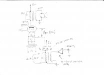
If I understand you correct than this my schematic approximately represent what you have done experimenting with GG power amp for audio use , but maybe I`m wrong .
Remember of one domestic HAM regulation that says that limited max.output radiated RF power is not the same for GG RF amp and for grounded cathode RF amp using the same output power tube , since by GG RF amp output power is approximately sum of power applied from RF exciter and generated power from GG RF amp itself , here both units works` in phase` , not out of phase as by grounded cathode RF amp, (from that old times I have few 2C39BA coaxial power triodes intended for UHF- RF GG amp.)
If I understand you correct than this my schematic approximately represent what you have done experimenting with GG power amp for audio use , but maybe I`m wrong .
Attachments
Last edited:
Your schematic is the correct representation of what I did several years ago,. except that I did not have the resistor or cap in the cathode circuit. The 833A requires positive grid bias for plate voltages below about 1KV, and works with zero bias around 1KV and needs negative bias above 1500 volts, depending on the tube. I simply adjusted the plate supply to gat about 100 mA of plate current.
Bias can be applied to the grid provided the grid is bypassed to ground for AC if a conventional tube is used.
Bias can be applied to the grid provided the grid is bypassed to ground for AC if a conventional tube is used.
Your schematic is the correct representation of what I did several years ago,. except that I did not have the resistor or cap in the cathode circuit. The 833A requires positive grid bias for plate voltages below about 1KV, and works with zero bias around 1KV and needs negative bias above 1500 volts, depending on the tube. I simply adjusted the plate supply to gat about 100 mA of plate current.
Bias can be applied to the grid provided the grid is bypassed to ground for AC if a conventional tube is used.
George thanks for your answer !
Got everything correct about bias of 833A power tube now,
but from my experience (RF) must say that is always better to leave grid (high Z input) tied on the ground , and to apply bias voltage on the cathode(low Z input) supplied from some low Z bias source , in case that you use driver transformer that can be done by disconnecting lower secondary wire from ground and to connect there variable bias source , with some exact value of positive bias voltage for `normal ` power tubes , or even some negative bias voltage value in case when 833A work with B+ under 1KV .
Any way I`m sure that very high quality SET amp can be done in this way (GG) , almost with ultimate quality , same as for GG- PP amp .
- Status
- This old topic is closed. If you want to reopen this topic, contact a moderator using the "Report Post" button.
- Home
- Amplifiers
- Tubes / Valves
- Common Grid design