Sorry for a longish first pose here, but it's a complicated question, for me anyway. I'm new to building (good sounding) amps, but not to tubes. I've repaired antique radios for years, sometimes replacing old tubes with new and making adjustments. But a SE pentode at 10% THD was about as far as the amp end went.
Anyway, just for the heck of it I decided to build an amp to plug an MP3 player into. A couple watts, enough to drive a small speaker. 2 12T10 compactrons, the dual-control pentodes (G1 and G3 connected together) as a long-tail pair, the beam side as a push-pull pair. A output transformer pulled from an old Conn organ I got for free and there you go. The design is strictly by the book, copied from schematics I found on the web and tweaked for the tube's characteristics. I can post a schematic if anyone cares. It works OK, 2 watts at 0.5% THD (better if I add NFB, but good enough without it) and easily driven to 2 watts with an IPod at 3/4 volume.
The problem is that there is a lot of heater hum. Heater for sure - 60Hz and running the heaters on an external DC power supply eliminates it. I know how to route heater connections, everything is twisted tight and lead well away from the rest of the wiring. The best I could find on the problem was at The Valve Wizard, which explains a bit about this circuit. The elevated cathode voltage on the long-tail pair seems part of the problem.
I tried elevating the voltage on the heater circuit as described, and it sort of works in a voodoo way. The cathodes on the long tail pair are at about 70V, at around 45 volts on the heater circuit the hum is minimized. But the actual hum waveform (on a scope) varies wildly with the voltage I use, it's not a simple "get's worse or get's better" kind of thing.
Which basically means I don't know how it works and I don't know what I'm doing, and so I don't trust it. Anyone out there know how I should approach this? If I could get rid of the hum it would be a nice toy, and the 12T10's light up in an impressive way making a cool conversation piece if nothing else
A hum waveform varying wildly with heater reference DC voltage could mean more than one mode of entry, and probably one of them being heater-cathode leakage.
A well balanced LTP and PP output stage should cancel out much of the hum if it is in phase on both sides, but will happily amplify it if it is antiphase. Try reversing the heater supply to one valve.
A well balanced LTP and PP output stage should cancel out much of the hum if it is in phase on both sides, but will happily amplify it if it is antiphase. Try reversing the heater supply to one valve.
One mistake I made with a valve amplifier was to mount the mains transformer too close to the valves. The valves were picking up stray magnetic fields.
One strange thing I did find was using an 12ax7 I was getting hum.
If I used the 12ax7 as consecutive stages I got zero hum but using only one stage I got a lot of hum.
For some reason the consecutive stages were cancelling out hum.
One strange thing I did find was using an 12ax7 I was getting hum.
If I used the 12ax7 as consecutive stages I got zero hum but using only one stage I got a lot of hum.
For some reason the consecutive stages were cancelling out hum.
Last edited:
All,
Thanks for the tips. Re SY's point, there was an issue with the grounding that I introduced when I rewired for 12 volt heaters. The original design used 24BF11 tubes, with a 24V center-tapped transformer (center tap grounded). I just moved one wire to the tap for 12 volts, so the heaters were grounded at one end, not the "center". Using a couple resistors to make a fake center and grounding it helped a bit.
Re "DF96" - this was a bigger issue and rather than waste words on the details I need to draw up some schematics, which will take a bit. Suffice it to say that a modification I made to allow negative feedback on the "follower" side of the long tail pair was introducing hum. When I just grounded the grid with a capacitor a large part of the hum went away.
It's now down to where the hum sounds barely louder than the hiss.
More work to do, and probably more questions, but let me get some diagrams up here first.
Thanks!
Schematic
Here is the schematic. The original "NFB input" network used a cap that was 10X smaller and resistors 10X larger. Redesigning it as shown had the biggest impact on the hum. Not sure entirely why, but I can see how lowering the impedance from gate to ground could do thus.
The rest of the design is pretty conventional, except that I use a 110v -> 24V(CT) transformer connected to a "backwards" 240/480V -> 24V transformer to get the B supply. You can get 24V control transformers of various voltage and power ratings dirt cheap on EBay, especially when compared to "real" tube power supply transformers.
Attachments
Can you show how you have the heaters wired?
The suppressor grid connection to the control grid- can you elaborate on that a bit?
And finally, you might consider wiring the screens together and using a single RC so that any noise there is guaranteed to be common mode. Minor point, but it saves two parts and potentially could increase noise rejection.
The 'T10 compactron is a combination of a beam pentode for audio and a "dual control" pentode intended (according to the spec) as an FM detector. I'm not familiar with this use. The "ordinary" control grid G1 has a tranconductance of 1000 uMho. The "suppressor" grid G3 is built as a less sensitive control grid with a trans of 400 uMho. All I can say is I tried it connected to the cathode and connected to G1 and found that the tube was more linear and showed higher gain then they were connected together. It assume it still works as a suppressor too.
I have a lot of compactrons (I surf eBay for bargains when I get bored) and most of them are special purpose tubes for TVs. You just have to take what you get and mess around with them sometimes. I've used them for several radio circuits. This is the first time as an amp and I'm basically guessing and measuring the results.
I'll try wiring the screens together tonight and see what it does. I'm also looking into making a CCS per MrCurwen's suggestion. I've found a tube that might work (trying to be a purist here, I probably have some HV transistors that would work too.)
In their EF86 data sheet, Mullard state that the heater-induced hum in that valve can be 3uV with one side of the heater circuit grounded, but this reduces to 1.5uV with a grounded heater centre tap. Not sure if this ratio would be typical for other valves in other circumstances.
I have noticed that as far as noise, hum and buzz are concerned, a small change in dB can make all the difference between 'annoying' and 'inaudible' because we are close to the threshold of audibility.
If a 'humdinger' pot is used to create an artificial centre tap, people often seem to find that the position for minimum hum can be well off-centre.
If you DC elevate the 'centre tap' then an electrolytic between the 'centre tap' and ground shunts any noise on the DC (and noise in the heater wiring).
Last edited:
The hum is gone, or gone enough for practical purposes since it's below the noise. Per M. Irving the final step was to put a pot across the supply instead of a pair of identical resistors, and connect the center to the power supply CT (through a cap). About 90% turned one way minimizes the hum. Farther the hum increases a bit. I can hear this and see it on a scope. A schematic of the power supply is attached.
As suggested I connected the screens together with one RC. I didn't make any difference at all, good or bad, in the sound, but it's two less parts in a crowded circuit, so I'm keeping it that way. I'm also still playing around with the NFB. At the point the gain is cut in half it pushes down the third harmonic 3 or 4 dB, but I'm not sure I could ever hear this (but it gives me an excuse to play with the spectrum analyzer in my Picoscope. When I was in grad school many eons ago a bleeding-edge spectrum analyzer was the size of a fridge, but I digress...) . More gain reduction than this and my CD player at full volume can't drive the amp to full power.
I may try the CCS idea for the LT Pair, but it's working well enough now for what I had in mind: driving a pair of small bookshelf speakers at a couple watts from an portable music player Now I need to think about how to build two amps small and neatly enough to fit in a nice wooden box on a shelf.
Thanks to all, I'm sure I'll have more questions as I get more into this.
Attachments
I noticed there is imbalanced AC heater current loads of 1.2 Amps vs .9 Amps with respect to center tap.....30 % AC offset...
I also noticed the .22uF cap at 60 Hz present a fairly high Z .... maybe try a mucho Bigger value to reduce HUM....
What if you connect the HUM pot across the entire 24V winding, instead of the the lower winding ??
Chris
I also noticed the .22uF cap at 60 Hz present a fairly high Z .... maybe try a mucho Bigger value to reduce HUM....
What if you connect the HUM pot across the entire 24V winding, instead of the the lower winding ??
Chris
Re Jaap and "mighty midget". Thanks for the pointer. Because in a LTP the grid and cathode are biased relative to a point far above ground I can't see an easy way to reproduce a fixed positive bias above the cathode on G3 like used in this amp. I went ahead and just used a battery between the cathode and G3 to bias it up 6V and certainly the voltage gain went way up, from about 25 to 40, but so did the distortion.
Anyway, it seems I'm stuck with either G1 or the cathode as the two reference points in a LTP. G3 tied to G1 seems to give about 1/2 the distortion at an output of 1V PP, relative to G3 tied to the cathode like a regular pentode. But contrary to what I said earlier, the gain is a bit better (30 vs 25) with G3 tied to the cathode.
And of course all of the operating points of the LTR circuit shift a bit when I change the connections, so maybe I'm just measuring a side effect. Beginning to think I should have started with something simpler.
Has anyone out there deeply analyzed "dual control pentodes". I haven't found anything really useful yet. It's hard for be to get my head around the characteristics I;m measuring.
Back to hum, which is why I'm here. It's OK now, but as long as I'm learning about things it's interesting to understand what's going on.
Per Chris' suggestion I put a 1K pot across the full 24V winding and connected the ground with a 0.47 uF. Didn't lower the hum much, but gave more space to adjust it. Also checked AC imbalance, but that's no issue here (0.05V off). The transformer is good for 4amp, so I think it would take a lot to imbalance it.
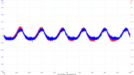
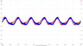
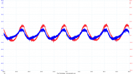
Grounding through the pot at any setting makes a huge reduction in the hum of course. Adjusting it to around the center minimizes the hum. But when I connected a scope to the grids on the P-P stage (no schematic, but it's totally by the book) I saw that the hum isn't actually reduced much at all, and it's pretty huge, ~100mv. The "best" point is simply where the two phases are best balanced.
Some scope traces attached. 10:1 probes so 10X on the voltages. "side 1" and "side 2" are all the way left and right, "best" is the least hum by ear (not looking at the scope).
Maybe this is pointing at a better way to reduce the hum? Now I'm just getting plain curious...
Per Chris' suggestion I put a 1K pot across the full 24V winding and connected the ground with a 0.47 uF. Didn't lower the hum much, but gave more space to adjust it. Also checked AC imbalance, but that's no issue here (0.05V off). The transformer is good for 4amp, so I think it would take a lot to imbalance it.
Grounding through the pot at any setting makes a huge reduction in the hum of course. Adjusting it to around the center minimizes the hum. But when I connected a scope to the grids on the P-P stage (no schematic, but it's totally by the book) I saw that the hum isn't actually reduced much at all, and it's pretty huge, ~100mv. The "best" point is simply where the two phases are best balanced.
Some scope traces attached. 10:1 probes so 10X on the voltages. "side 1" and "side 2" are all the way left and right, "best" is the least hum by ear (not looking at the scope).
Maybe this is pointing at a better way to reduce the hum? Now I'm just getting plain curious...
Attachments
- Status
- This old topic is closed. If you want to reopen this topic, contact a moderator using the "Report Post" button.
- Home
- Amplifiers
- Tubes / Valves
- New to amps - Long-tail pair and heater hum