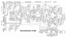
Based on your description, I would begin by monitoring the the B+ output of the power supply with an oscilloscope. Start at the output of the voltage doubler and proceed outward to the following nodes in succession. The object it to determine which (if any) filter cap sections are going bad, of if the doubler itself is failing.
I would also pay close visual attention to the four 6L6 output tubes looking for signs of overheating. That's red plates or screens. And since the four cathodes are all connected together to a common bypass capacitor, one channel output could possibly affect the other. The delay through heating sounds like a tube problem. Also look for overheated resistors at the filter capacitor nodes.
I would also pay close visual attention to the four 6L6 output tubes looking for signs of overheating. That's red plates or screens. And since the four cathodes are all connected together to a common bypass capacitor, one channel output could possibly affect the other. The delay through heating sounds like a tube problem. Also look for overheated resistors at the filter capacitor nodes.
Attachments
Last edited:
Thanks for the good ideas. I don't have an oscilloscope but I did test capacitors. One whole can containing 4 supply capacitors is out with all measuring 0uf. One of the voltage doubler caps has some swelling at the ends but still measures correctly. I just hope the power transformer isn't faulty. I did measure voltages which appeared to be expected. I ordered some capacitors to replace the faulty ones hopefully thats all it is I would hate to lose this gem
Could be thermal runaway in an output valve, triggered either by a gassy valve or a leaky coupling capacitor. Check the 0.05uF caps feeding the output grids, by monitoring the grid voltage. In this unusual design it will be a bit +ve, but it should not increase by much as the valves warm up.
I found the problem. I powered the amp up and waited 5 minutes and sure enough the hum started. So I began taking voltage measurements all over the place. Found a higher voltage
and traced it to a 12au7. When I applied the test to the plate(I think) the voltage read 270V! supposed to be around 100v. Bad tube. Some kind of massive failure as both sections of the tube read 270v. I switched out the 6l6s when it first happened with a whole new set. I Didn't think it was a signal tube. Maybe next time I will take the simple approach and switch out all the tube first.
and traced it to a 12au7. When I applied the test to the plate(I think) the voltage read 270V! supposed to be around 100v. Bad tube. Some kind of massive failure as both sections of the tube read 270v. I switched out the 6l6s when it first happened with a whole new set. I Didn't think it was a signal tube. Maybe next time I will take the simple approach and switch out all the tube first.
- Status
- This old topic is closed. If you want to reopen this topic, contact a moderator using the "Report Post" button.
- Home
- Amplifiers
- Tubes / Valves
- Trouble shooting vintage Harman Kardon A250