Also, checked again my signal voltage against the simulator prediction and there is really lots of difference there; to get 1W output with 5K OT into 8ohm I have 29V on #45 grid while simulator calculates 40V; really not sure where this difference comes from; really looks as if there is a mistake in the simulation program?
my amplification on #45 is 2.7; exactly same as predicted by simulation program...
As noted, simulations are not absolute. I just checked some NOS 45 triodes in a simple SE design with a 5K load and a 12AT7 input/driver. For 1-watt output it's about 84 volts peak-to-peak on the grid, or 29.8 volts RMS. The sim is likely showing 40 volts as the swing from static (which would be 42 volts per my actual measurement). This value needs to be doubled as you swing the grid by this amount positive and negative.
As an aside, the Glass-ware SE Amp CAD program shows about the same... a 39-volt grid swing for 1-watt output. You just need to do the conversion, which is double the voltage and divide by 2.818 for RMS.
As per the distortion figure... what is the condition of your 45 triodes? Do you have others to swap in? I've found some heavily used 45s that have pretty high THD, while truly NOS ones can be quite low.
Regards, KM
OK, understand, so the U-in from the simulation is actually 1/2 of V-pp, not V-rms; makes sense.
I really do not think that distortion I am seeing has to do with actual tubes; I got four 45's and two look really as they are NOS. Still, they all get very similar THD measuraments; basically just over 1% at 0.1W, 2% at 0.5W, 3.5% at 1W and 4.5% at 1.5W.
As I made this amp to be switchable and take also #10/#45 as well as #10/VT52 combinations I did measure ad compare those as well.
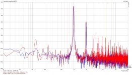
I was surprised to see basically same distortion figures for #10/VT52 combo as I was sure those would be less; here I enclose the spectrum comparison of #26/#45 (in red) vs. #10/VT52 (in blue); this is measured at 0.5W-Pout. Second order distortion is identical while #10/VT52 has a bit less 3rd and higher order. Here VT52 was real actual NOS, still in un-opened military box.
#10/VT52 version is running at 275V plate/18mA/-16V bias on #10 and 290V plate/43mA/-55V bias on VT52.
I am still thinking if there might be a "bug" in the actual design that would cause this pretty high THD, over 1% at 0.1W out.
Could it be something about a behavior of directly coupled topology that I am overlooking / not understanding?
Maybe best next step would be to modify design and test in simple capacitor coupled configuration, using same tubes at same operating points.
It is comparison to my IT coupled 211 amp that manages 0.067% THD at 0.5W (vs.2% on new amp) that makes me think I should be able to improve this design.
I do realize that there is some even order distortion cancelation happening in 211 amp (visible from relatively lower 2nd and 4th order distortion than 3rd and 5th order), but I am not really sure from where this comes as it uses simple 5687 as a driver, IT coupled to 211 that has grounded cathode and fixed (adjustable) negative bias on the secondary of IT.
I really do not think that distortion I am seeing has to do with actual tubes; I got four 45's and two look really as they are NOS. Still, they all get very similar THD measuraments; basically just over 1% at 0.1W, 2% at 0.5W, 3.5% at 1W and 4.5% at 1.5W.
As I made this amp to be switchable and take also #10/#45 as well as #10/VT52 combinations I did measure ad compare those as well.
I was surprised to see basically same distortion figures for #10/VT52 combo as I was sure those would be less; here I enclose the spectrum comparison of #26/#45 (in red) vs. #10/VT52 (in blue); this is measured at 0.5W-Pout. Second order distortion is identical while #10/VT52 has a bit less 3rd and higher order. Here VT52 was real actual NOS, still in un-opened military box.
#10/VT52 version is running at 275V plate/18mA/-16V bias on #10 and 290V plate/43mA/-55V bias on VT52.
I am still thinking if there might be a "bug" in the actual design that would cause this pretty high THD, over 1% at 0.1W out.
Could it be something about a behavior of directly coupled topology that I am overlooking / not understanding?
Maybe best next step would be to modify design and test in simple capacitor coupled configuration, using same tubes at same operating points.
It is comparison to my IT coupled 211 amp that manages 0.067% THD at 0.5W (vs.2% on new amp) that makes me think I should be able to improve this design.
I do realize that there is some even order distortion cancelation happening in 211 amp (visible from relatively lower 2nd and 4th order distortion than 3rd and 5th order), but I am not really sure from where this comes as it uses simple 5687 as a driver, IT coupled to 211 that has grounded cathode and fixed (adjustable) negative bias on the secondary of IT.
Attachments
Well, I grabbed my old DC coupled 45 SE amp (which has been in constant service for about 8 years) and put it on the test bench. It uses a 6SF5 input/driver directly coupled to the 45 with a 5K Magnequest RH40 OPT. Distortion measurements at 1000Hz on a HP 334a are as follows:
100mw = 0.40% THD
500mw = 1.10% THD
1.00W = 1.65% THD
1.50W = 2.25% THD
Regards, KM
100mw = 0.40% THD
500mw = 1.10% THD
1.00W = 1.65% THD
1.50W = 2.25% THD
Regards, KM
Attachments
Thanks a lot for doing this; it really helps to get a benchmark comparison!
Can you see with your measuring setup how much of that is 2nd order your design gets?
I have a feeling that my 2nd order is higher then it should be; but this assumption is based on my comparison against IT coupled 211 amp...
Can you see with your measuring setup how much of that is 2nd order your design gets?
I have a feeling that my 2nd order is higher then it should be; but this assumption is based on my comparison against IT coupled 211 amp...
Well, I grabbed my old DC coupled 45 SE amp (which has been in constant service for about 8 years) and put it on the test bench. It uses a 6SF5 input/driver directly coupled to the 45 with a 5K Magnequest RH40 OPT. Distortion measurements at 1000Hz on a HP 334a are as follows:
100mw = 0.40% THD
500mw = 1.10% THD
1.00W = 1.65% THD
1.50W = 2.25% THD
Regards, KM
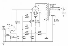
The schematic looks fine you have some degenerative feedback on the final but no neg feedback! but you bypassed the gain/driver.... if you take off the bypass and add some neg feedback...your measured and heard distortion will vanish to somewhere around .7thd

Correct, no negative feedback by design. It was a quick and simple amplifier put together simply as a test around the 45 and SE, albeit a bit of inspiration from the Fi amps. I use them to drive a pair of Fostex F120a drivers for some background music in the family room, that's all. I've no desire to make any changes to it but thanks for looking.
My other 45 amps are also SE, zero feedback, much better and a clean sheet design using all Hashimoto iron and no electrolytic caps. They are not DC coupled to the 45, but the input/driver is DC coupled, hence a single coupling cap. The distortion (THD) on these is quite low, being less than 0.4% at 1-watt output and within 1dB to 50KHz. They also have better linearity, lower output noise (>80dB below 1-watt) and a bit more power, 2.25 watts vs 1.75 watts ;-)
Regards, KM
Is there a chance that you would be willing to share your improved #45 design; since I am still in prototyping stage I would be willing to give up DC coupled idea.
Was thinking about going with IT, but since I do not have a free IT to test would need to purchase it just to test.
Would be really keen to see if I could reduce THD in my design before getting it finely built.
Any suggestions are welcome!
Was thinking about going with IT, but since I do not have a free IT to test would need to purchase it just to test.
Would be really keen to see if I could reduce THD in my design before getting it finely built.
Any suggestions are welcome!
Problem found!
So, I did track down reason for my high THD of just over 1% at 100mW compared to 0.4% similar DC coupled designs are getting.....my driver is simply too clean, offering not enough even order distortion cancelation.
Found this by purposely loading the driver down by connecting the plate of #26 to ground trough 8.2K resistor in series with capacitor.
As expected my driver gain went down a lot and distortion in the driver increased compared to original circuit where there is a 270H choke load on the driver....the final result, my THD at 100mW on the speaker terminal went from 1.1% to 0.16%!!!
The question is if purposely increasing distortion in the driver to get more cancelation on the output is the "right" way to improve the design?
I could wire my choke windings in parallel and reduce it from 270H to 67.5H which would reduce the load on the driver, decrease it's distortion and probably result in lower THD on the output....but would this really sound better?
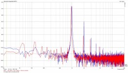
One can see from the attached comparison of the original measurement at 100mW (in blue) and new, with reduced load on the driver (in red) that there is about same dB reduction on the second order as there is increase in the third order, but total THD went down from 1.1% to 0.16%.
I guess, best would be to focus on reducing actual distortion on the output stage and not trying to increase THD on the driver to get the cancelation effect.
I tried increasing the load on #45 by using 15ohm resistor across the speaker terminals instead of 8ohm and did see a reduction in THD; at 100mW THD was down from original 1.1% into 8ohm to 0.73% into 15ohm.
I will try connecting some 10K OT's that I got and see how it comes out.
So, I did track down reason for my high THD of just over 1% at 100mW compared to 0.4% similar DC coupled designs are getting.....my driver is simply too clean, offering not enough even order distortion cancelation.
Found this by purposely loading the driver down by connecting the plate of #26 to ground trough 8.2K resistor in series with capacitor.
As expected my driver gain went down a lot and distortion in the driver increased compared to original circuit where there is a 270H choke load on the driver....the final result, my THD at 100mW on the speaker terminal went from 1.1% to 0.16%!!!
The question is if purposely increasing distortion in the driver to get more cancelation on the output is the "right" way to improve the design?
I could wire my choke windings in parallel and reduce it from 270H to 67.5H which would reduce the load on the driver, decrease it's distortion and probably result in lower THD on the output....but would this really sound better?
One can see from the attached comparison of the original measurement at 100mW (in blue) and new, with reduced load on the driver (in red) that there is about same dB reduction on the second order as there is increase in the third order, but total THD went down from 1.1% to 0.16%.
I guess, best would be to focus on reducing actual distortion on the output stage and not trying to increase THD on the driver to get the cancelation effect.
I tried increasing the load on #45 by using 15ohm resistor across the speaker terminals instead of 8ohm and did see a reduction in THD; at 100mW THD was down from original 1.1% into 8ohm to 0.73% into 15ohm.
I will try connecting some 10K OT's that I got and see how it comes out.
Attachments
I think you are on the right track.. I generally aim for the cleanest driver I can make and then either live with the distortion of the output stage or if excessive I will attempt to reduce it. The first step might be to try the earlier suggestion of applying a 16 ohm load on the 8 ohm tap and seeing what happens. I would expect at least a few dB reduction in distortion everywhere.
Yes, I agree that purposely increasing distortion in the driver just to get more cancelation does not sound right, so what I need to try is to reduce distortion in the output stage.
I did try loading the OT with 15 instead of 8 ohm on secondary and did get some reduction, but I am wondering if there might be any other way to do this.
Is there a modification to the circuit that would help lower the output stage THD?
Was even thinking about going with Para-fed output stage, but not sure about that idea...
Yes, I guess push-pull would be possible approach, but would like to stay with SE...
I guess trying to lower output impedance of the driver (for example adding a "Power-drive" stage like George uses in Tubelab SE design) would only help distortion near the point where 45 grid starts drawing current; at 0.1W output should not really make the difference?
I guess trying to lower output impedance of the driver (for example adding a "Power-drive" stage like George uses in Tubelab SE design) would only help distortion near the point where 45 grid starts drawing current; at 0.1W output should not really make the difference?
I tried increasing the load on #45 by using 15ohm resistor across the speaker terminals instead of 8ohm and did see a reduction in THD; at 100mW THD was down from original 1.1% into 8ohm to 0.73% into 15ohm.
I will try connecting some 10K OT's that I got and see how it comes out.
I did tell that few posts back. So your problem are your 45's. If you go for 10K your Pout will be quite lower.
Regarding 2nd harmonic cancellation, IME, if this doesn't bring other harmonics, doesn't cause higher IMD and doesn't limit the driver for larger swing it will sound better. These are the criteria I have found to to work for a better sound. Have a go and listen to it before discarding is the best advice I can give you here.
The other way you have to reduce distortion, if you don't want to go PP, is feedback.
I suspect it is partly the nature of the beast, the driver is extremely linear, and the output stage which is working much harder is less so. One other possibility if you don't mind running the 45s a bit harder is to up the plate current temporarily and determine whether or not the distortion decreases slightly.
Since the numbers do not vary appreciably with other output tubes in use is it just possible that the output transformer as well regarded as it is might be part of the problem?
Try placing a large 5K resistor across the primary and put a couple of hundred ohms across the secondary so it provides insignificant loading. See what result that gives. Can you borrow an output transformer from someone else for a quick test?
Were the results not fairly consistent with your other tube combination I would suspect the 45s were tired, but since that's not the case I don't...
Thanks for suggestions, will try both options and see what I get; one will be to rewire #26 plate choke with windings in parallel that will reduce it's inductance from 270H to 67.5H and will then compare the spectrum as well as IMD to see what I get.
I will as well try transformer test as Kevin suggests with 5K across the primary and few hundred across secondary; will be really interesting to see the result there. I do have a second XE-20S to test; will try changing them just in case something is wrong with this one particular OT.
I will also hookup my 10K OT, jut to test and see what happens; will try that with 8 and 4 ohm on the secondary.
I am really pretty sure it is not a particular #45 tube as I get virtually same results with any of the 4 tubes I tested, and then, when switching to 10Y/VT52 configuration (and using really NOS VT52) I get again almost the same spectrum plot and THD; the only really noticeable difference is that with 10Y instead of #26 there is no 60Hz/120Hz and their harmonies present.
When you do the test with distortion cancellation it is important that you test it at different frequencies as the cancellation might change, and generally will, with frequency. Tests at 100Hz, 1KHz and 10KHz should be enough to assess how it works. This is another condition, in addition to the previous criteria, to fix the amount to cancel or even find that it only works in a limited range and for the rest is a lot worse.....in such case I would say (but you can verify by listening as well) that it is not convenient.
- Status
- This old topic is closed. If you want to reopen this topic, contact a moderator using the "Report Post" button.
- Home
- Amplifiers
- Tubes / Valves
- Distortion expected in SE DC coupled 26/45 amp