For anyone who has built it, what is the value of C1? I dont see it listed in the manual.
There doesn't seem to be a C1, do you mean C11? That would be several 10s of uF.
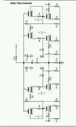
On the posted schematic C1 sits between R12 and R10. In parallel to C11 and C2
Oh yes, that's the hum canceling circuit for the current sources. It passes hum from the B+ to the two grids through the resistor divider.
The C1 should set a corner of 5Hz or less (so as not to cause too much phase shift at the hum frequencies) with the series sum of R13 and the resistor below it.
That resistor is misnumbered as R10. It is not the same value as the two R10 grid stoppers.
.1-1 uf according to the other designs
The capacitor value depends on the resistors that it feeds.
So the values are R11-1k and R10-88.7k
You need to know the two resistors directly below the C1, which are labeled R10 and R13. (That R10 is not the same value as the R10s on the grids, it's a numbering mistake.) Add the R10 and R13, and then set the capacitor C1 value so the corner is below 10 Hz. C1 = 1 / ( 2 x 3.14 x 10 x ( R10 + R13 ) )
- Status
- This old topic is closed. If you want to reopen this topic, contact a moderator using the "Report Post" button.
- Home
- Amplifiers
- Tubes / Valves
- Aikido 12VAC Help needed