BTW, I'm pretty sure the tubelington is a red herring. Based on posted tubelington curves, linearity appears no better than an unassisted valve, worse if anything IMO. The principle of the OP is that the valve itself is capable of being extremely linear indeed under the right conditions - as DF96 also posted here concerning the innocent ECC83 !
"BTW, I'm pretty sure the tubelington is a red herring. Based on posted tubelington curves, linearity appears no better than an unassisted valve, worse if anything IMO."
The tubelington just multiplies the current, so no linearization over what the tube would normally do (at the lower current). If one tried to get the higher multiplied current from the tube though, it would really be non-linear.
Putting the larger emitter resistor in should linearize the gain though, since it just converges on a cathode follower driving a linearized V to I converter. But it will have high Zout that way. The effectively degenerated tube cathode makes the plate feedback less effective.
From the AC equivalent circuit point of view there is no difference in having the plate resistor connected to B+ or ground. As such, the distortion will be determined by the active device (cascode, pentode) and the load resistor.
In the case of the plate resistor connected to B+ you have the power supply in the signal loop. Any noise on the power supply is added in series with the signal. With a cascode or high plate resistance pentode the PSRR approaches zero.
In the case of the plate resistor connected to ground the power supply is not in the signal loop. Any noise on the power supply is attenuated by the ratio of the CCS impedance divided by the plate resistor value. With a good performing CCS the PSRR ratio of the circuit can be very high, unlike the standard circuit with the plate resistor to B+.
The AC performance of the 2 circuits below is equivalent. The difference is in the PSRR.
An externally hosted image should be here but it was not working when we last tested it.
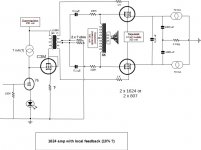
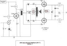
I wonder if this principles can also be used with a IT coupled amp. I am contemplating about these 2 versions of an idea for such an amp
Attachments
I wonder if this principles can also be used with a IT coupled amp. I am contemplating about these 2 versions of an idea for such an amp
The interstage driver in version 1 would work but would require a bypass capacitor on the cathode of the C3M.
Version 2 would not work as drawn. The DC resistance of the interstage primary would load down the bias point.
Version 2 could be setup as a parafeed stage by connecting the the primary of the interstage transformer to the plate and cathode of the C3M with a capacitor on one of the primary leads.
The problem is, we amplify power. That means any load worsens the linearity. We need more amplification (like a follower with deep negative feedback by voltage) to save this linearity adding more non-linearity by a follower that is loaded and has at least current transfer function dependent on resistance and signal itself.
No free cheese in the real life, except in a mousetrap.")
No free cheese in the real life, except in a mousetrap.
Indeed.The problem is, we amplify power. That means any load worsens the linearity. We need more amplification (like a follower with deep negative feedback by voltage) to save this linearity adding more non-linearity by a follower that is loaded and has at least current transfer function dependent on resistance and signal itself.
No free cheese in the real life, except in a mousetrap.
Looking at the circuit Gary G posted a few posts ago, it has a CCS anode load Is and 47k resistor load to ground RL - here's demonstration of the effect of that load versus the ideal infinite impededance load in the OP:
Definitions as per the OP, plus new terms:
Is constant current source
RL load resistance
RL has current Va/RL
Modifying the transfer relation set out in the original post
Is - (Va/RL) = P[Vg + Va/µ]n
Rearranging
Vg = (Is/P - Va/PRL)1/n - (Va/u )
Define convenient constants a and b
a = Is/P
b = PRL
Differentiate to obtain transfer characteristic
dVg/dVa = - ((a - Va/b)(1/n) - 1)/ bn) - (1/µ)
The first term represents non-linearity, deviation from the ideal second term 1/µ. In this case, it depends upon RL and tends to zero (ideal) as RL increases in value. Zero harmonic distortion conditions are when RL is infinite, or when n is 1 ie the valve is linear.
It's possible to extract the constants involved from published datasheets by reading the curves appropriately. Doing this for the 6BQ5 in Gary P's circuit and plugging into equations above suggests the distortion term might amount to c 0.15% for RL = 47k as per the schematic. Which seems good and practical IMO. This would be c 0.0015% for RL = 4.7M in principle.........
- Status
- This old topic is closed. If you want to reopen this topic, contact a moderator using the "Report Post" button.
- Home
- Amplifiers
- Tubes / Valves
- CCS anode load overcomes 3/2 law non-linearity