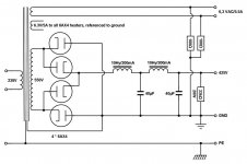
I am building the 6v6 preamp by Salas for the 3rd time and would like to try this configuration that is endorsed by both Thomas Meyer and Lynn Olsen. I have played around quite a bit with PSUD in an attempt to understand how to best implement this idea. In his blog, Thomas shows the 6ax4 bridge loaded with a 10H, 40uF, 10H, 40uF with bleeder resistor. Sims support the need for 100-120V of headroom due to voltage drop across the tubes. This is not a problem as the transformer can be made to order. The problem I am having is getting rid of the ringing. I need 350-360VSSH at 100mA to feed two SSHV2's for the two channels. Thanks for your help.
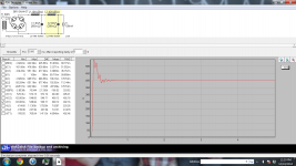
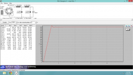
Here is the PSUD screenshot showing the ringing. I amusing specs from Lundahl 1651 transformer for the simulation. The chokes are Lundahl 1638. Caps are motor run 40uF.
https://dl-web.dropbox.com/get/Scre...AAbynhkHP6AG1dCw8wd8WghOAc3gZ0WxpNeGtWglY4afw
https://dl-web.dropbox.com/get/Scre...AAbynhkHP6AG1dCw8wd8WghOAc3gZ0WxpNeGtWglY4afw
For whatever reason, screen print will not work unless Dropbox pics it up. I'll repost raw pic when I get back to the computer.
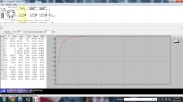
Of course, adding and RC stage in front of the choke, makes for a pretty graph, but I wanted to investigate the magic behind pure choke loaded rectifiers. Perhaps it raises another question. What are the benefits of a choke input vs pi filter.
Of course, adding and RC stage in front of the choke, makes for a pretty graph, but I wanted to investigate the magic behind pure choke loaded rectifiers. Perhaps it raises another question. What are the benefits of a choke input vs pi filter.
Sim
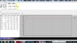
Here it is. Second shot shows difference as a result of loading the second choke with much higher capacitance. Smooths is out a bit, but still have overshoot. Last one is with RC in front. With RC use, transformer is over spec'd
Here it is. Second shot shows difference as a result of loading the second choke with much higher capacitance. Smooths is out a bit, but still have overshoot. Last one is with RC in front. With RC use, transformer is over spec'd
Attachments
Last edited:
They are Lundahl 1638. I had planned to go full dual mono, using one on each channel, but saw the 6ax4 bridge and though i would play around a bit. I am trying to learn the advantages and disadvantages of both appraoches.
Found this as a general explanation of the differences. Seem counter intuitive to what PSUD is showing.
Choke or Capacitor Input?
Found this as a general explanation of the differences. Seem counter intuitive to what PSUD is showing.
Choke or Capacitor Input?
I am using the SSHv2 for a regulator and want to keep that, so ill have to try one of the others. I assume that since you did not include adding series resistance as an option, you do not think this is a good idea. That would seem to leave only the snubber option, as i see no point in using lower quality chokes, but perhaps this is improper thinking.
A low quality choke is likely to be cheaper, smaller, and lighter than a high quality choke in series with a power resistor.
As a first rough estimate of the resistance you need to do effective damping just calculate sqrt(L/C). The ringing frequency will be roughly 1/(2 pi sqrt(LC) ). Interactions between components, and the switching of the rectifier diodes, mean that these are only estimates but they will give you an idea of what you are dealing with.
Note that the second try above (with the 160uF smoother) probably doesn't change the ringing in the first stage but just acts as a low pass filter so the output sees less of it.
I already have the Lundahl chokes, so I would like to use them. You are correct that adding a much larger second cap only improves the resutls across the CC source on theouput. C1 is still ringing like a bell.
l must admit i do not understand the use of this arrangement in this PSU. I guess it is safe to assume that he is either having his transformers wound custom to prevent ringing or is accepting it.
l must admit i do not understand the use of this arrangement in this PSU. I guess it is safe to assume that he is either having his transformers wound custom to prevent ringing or is accepting it.
Attachments
Hi!
I assume that you are talking about me, when you write 'he'.
Maybe instead of running simulations it would be better to actually build things and see the real life behaviour.
You are looking at the circuit out of context. In my designs they are always followed by another LC stage
- I am not using the same chokes you are using
- still you will not see that ringing in the actual circuit
- turn on the soft start option to emulate the warm up behaviour of the 6AX4
Best regards
Thomas
Last edited:
Hi!
The tubes will not conduct instantly, they have about 30sec warm up time and will start to conduct gradually. This can be emulated by activating the soft start option in PSUD.
The example you picked is meant for power amps. Maybe not the best choice for a preamp supply. Also if you use a regulator, maybe you don't need LCLC.
But if you have the parts on hand. why not build it and see what it does.
Best regards
Thomas
I had originally intended a single LC circuit with true dual mono set, but reconsidered when i saw your psu arrangement. I must admit that after seeing the filtering ability of the LCLC circuit, i questioned whether or not the shunt was necessary. It is within reason to test both ways. As for unnecessary, this is DIY") , that being said, i want what will be beneficial. I am not just a measuremtns guy and enjoy subjective impressions as well. Perfect audiophile material
, that being said, i want what will be beneficial. I am not just a measuremtns guy and enjoy subjective impressions as well. Perfect audiophile material
, that being said, i want what will be beneficial. I am not just a measuremtns guy and enjoy subjective impressions as well. Perfect audiophile materialYes, ringing might not matter too much if there is nothing to excite it.Vinylsavor said:The tubes will not conduct instantly, they have about 30sec warm up time and will start to conduct gradually. This can be emulated by activating the soft start option in PSUD.
Thank you Thomas. You are correct. I did not consider the slow ramp of the rectifier tube. I normally just build something, but being the first time using choke input, I was unsure and wanted to sim a wee bit first. Still a little overshoot, but this make me comfrtable with trying.
Attachments
- Status
- This old topic is closed. If you want to reopen this topic, contact a moderator using the "Report Post" button.
- Home
- Amplifiers
- Tubes / Valves
- Choke loaded 6ax4 bridge