I read people want to go through a lot of trouble to get DC coupling in tube power amp. I can see the only time it makes the different is if you drive the next stage to conducting grid current................Don't!!!
Is it true that the reason people think it's more important to have DC coupling from LTP to power tubes is mainly because of to possibility of the power tube is driven into conducting grid current and charge up the coupling cap and create blocking effect? I just don't understand people want to consider Class AB2( drive to grid conduction) in audiophile amp. In my book, you want low distortion, don't do that!!!
Please tell me what am I missing.
Have you searched at all? In the past week or 2 you have started many threads where you basically demand that somebody explains directly to you all the leading edge stuff that been discussed on this forum in the last 15 years. Don't you think it would be a little more polite and professional to search at least a little first?
I just don't understand people want to consider Class AB2 (drive to grid conduction) in audiophile amp. In my book, you want low distortion, don't do that!!!
Please tell me what am I missing.
That applied back in "the day". Back then, 'AB2 was used where you wanted lotsawatts, and fidelity was a secondary consideration. Otherwise, it was used mainly for RF amps where harmonic distortion wasn't a consideration since plate loads were LC tuners that loaded plates very heavily at off-resosnace, and there were usually more BPFs, tuners, "Match Boxes" between the amp and the antenna.
Times have changed considerably. Now, you can use a power MOSFET as a source follower to slap those gtids silly. The source follower has a way lower Zo than any hollow state solution, nor does it require IST coupling. That way, you can use types like the 811, 812, 814, 1624 -- all RF triodes and pentodes designed for very low IP at Vgk= 0. Some of these are still in production, and go for higher than expected prices due to audio demand.
Source followers are sonically transparent if you make certain you keep that vds up and out of the nastily non-linear region of Crt.
I read people want to go through a lot of trouble to get DC coupling in tube power amp. I can see the only time it makes the different is if you drive the next stage to conducting grid current................Don't!!!
Is it true that the reason people think it's more important to have DC coupling from LTP to power tubes is mainly because of to possibility of the power tube is driven into conducting grid current and charge up the coupling cap and create blocking effect? I just don't understand people want to consider Class AB2( drive to grid conduction) in audiophile amp. In my book, you want low distortion, don't do that!!!
Please tell me what am I missing.
That all comes down to the usual business of simplifying things too much without looking at the specific conditions and applications.
First grid current in vacuum tubes starts when the grid is still negative, this is actually a critical point also with the 12AX7 if you want to use it to swing a lot of volts, and if you want to use the full capability of the amplifier you need to take into account what it does to the signal. There is an old article by Chrowhurst that explains it all.
Secondly, I happen to have a 45 PP amplifier which is nominally the 5.5W Class A as from datasheet.
http://frank.pocnet.net/sheets/084/4/45.pdf
You can see in the first column of the AB2 page that just having the right driver, with exactly the same quiescent conditions and OT, it will provide up to 17W at 5% THD. It will clip so softly that all those watts are pretty usable on short and strong transients. It makes a lot of difference in comparison to the same amp with RC coupled driver. Actually, another planet having some additional 4 dB headroom.
Less capacitors means less poles. Keeping phase shift small when feedback (global) is used helps stability.
You bet!
Amplifiers that oscillate and oscillators that amplify are HIGHLY undesirable. Satisfy the Barkhausen criterion, only when appropriate.
Another good reason for DC coupling is the fact that the dielectric materials used in caps. are imperfect. Unwanted colorations can be introduced by caps. in the signal path.
Please tell me what am I missing.
Data and experience with AB2.
Shoog puts it best with the little phrase, “you either accept or reject the notion that a capacitor in the signal path has a sonic impact”. Its a schizophrenic world, on this issue. Veritably bipolar.
Insofar as I have seen (so far … 40 years in, who knows how many left to go…) remarkable amounts of design "engineering" and "workarounds" and "compromises" are put into play when trying to eliminate those nasty old capacitors. But, why were capacitors ever fingered as being nasty to begin with?
My own theory is that they're one of only 2 of the components that make up an amplifier that actually gracelessly age. Or used to. Paper-oil caps become lossy, very much as if there is a high (but not high enough to disregard) resistor in parallel with 'em. So, since nominally they're either strapped into "blocking DC, letting AC thru" mode, having that parasitic lossy resistor, kind of ruins everything. And the ruination can range from barely perceptible, to hugely horrible, if significant DC current flows past the cap.
Also - and often more cited than I think is actually warranted - there are capacitive non-linearities … where the capacitance of the capacitor varies with its bias voltage. I'm not sure of old-timey dielectrics such as a dry paper, mica, crâppy film plastics of the pre–1970s had much nonlinearity, but one type in particular - the compact ultra-high dielectric constant disk "ceramic" capacitor sure did. And does! Since a large herd of audiophile advocates drink from the font of "all things linear are good, and all non-linearities are BAD", well… the little cheap, cappuccino brown disk caps … are verboten. OK.
This is why some struggle to buy capacitors that have magically exotic construction and properties. They are not in the camp that completely eschews caps, but are amongst the hobbyists that are competent enough with a soldering iron and a credit card, to order up a whole bundle of gold plated, copper foiled, German multilayer filmed, aggressively tightened, hermetically sealed, tissue wrapped, and presentation boxed capacitors that run north of $100 apiece. And, they solder the things in, power up, and Lo! The once magnificent amplifier now sounds airy, transparent, with 3-D sound staging, utterly amazing instrument placement, and the near-removal of any influence that the speakers once had on things. Yah, baby!
The other camp though - those with either the abstraction-interest to embark on a journey to find (and buy / build) sound-path capacitor-free amplifiers, or those with the engineering cajunas to assess, contemplate, draw up, and integrate various cap-free design options into their Next Sweet Amp … go that route. THESE two reasons, while similar in result, are what bring forth all the variously competing signal-path-cap-free designs; they in turn have all sorts of tradeoffs that aren't much writ up, or much appreciated beyond the VERY small band of people who can actually numerically model things with accuracy and experience.
I personally don't give a flea's tail-feathers whether there are quality (but not extreme) capacitors in the audio food chain. MODERN units are so wickedly better than things we were buying as late as the 1970s, as to make the whole "nonlinearity" argument basically moot. And, for that matter, (with a big exception for electrolytics!) virtually without the probability of developing "leaky cap" characteristics.
I put italics around the electrolytics because they are fundamentally different in construction to wound capacitors: they have a sintered block of porous aluminum (foil or otherwise) that rests in an a liquid electrolyte. In manufacturing, the manufacturer impresses a well regulated, strong voltage on the just-built cap. They have no capacitance to start with, but quickly form a thick and nearly impermeable layer of oxide on the surface of the positive(?) aluminum structure. This is an insulator. When the voltage is removed, after a little thermal annealing, the capacitor now has a "permanent" capacitance. However, the oxide is quite thin, and the electrolyte mightn't be done electrochemically having its way with the device, especially over years both of service and disservice.
I really didn't intend to write up this much stuff, but … it is what it is.
I'm in the "not afraid of the little bad caps" nursery-rhyming school. Modern caps introduce DC-blocking that is remarkably good at allowing individual stage design to be fairly well optimized without having to compromise it terribly with chained-stage DC bias effects. Or, in English: amps with interstage caps (or interstage transformers, coming back in vogue I hear!) “play more nicely” when they fail. Perhaps the only response to that is, "who cares?" because there are these things called fuses … that also help.
Dunno.
Camps.
Caps.
GoatGuy
I understand about caps in the signal path. I gave it a lot of thinking and I posted a thread in the "Parts" part of this forum. I made my argument that as long as it is for DC blocking and use over size ( value) cap, it's not important. Here is the link to the thread and I did math analysis to back my statement up in post #15.
http://www.diyaudio.com/forums/parts/265925-question-different-type-capacitors-2.html
Bottom line, yes, cap has distortion, no doubt about it. BUT for DC blocking, use cap large enough so the reactance is very low compare to the resistance of the circuit, you will not have a problem. Although you have to be careful using caps for stability, pole and zeros or tone stack.
As for DC charging due to grid current, which part is the most important? Is the input to the power tube have more problem with charging as grid current is highest compare to the LTP or input stage. I know everything is important, but it has to give somewhere. I just did a first pass design with total DC couple. It is doable, BUT the DC of the first stage is going to affect the power tube. That means any drift from the first stage is going to be amplified and cause big drift to the power tubes. This is not wise unless you do DC servo, which again more complication.
JMHO
Alan
Last edited:
DC coupled amps tend to settle into fairly stable behaviour if they are designed right. All my PP amps are DC coupled and they work fine if the tubes start off reasonably well matched. Its not such a big deal to design DC coupled amps if you aren't afraid of input transformers and negative supplies.
I can certainly attest to the fact that capacitors are not totally transparent and every cap you add to the signal path tends to wash out a bit more detail. Still the effect is small and not worth spending huge money on exotic parts.
Is it worth it, maybe.
I can certainly attest to the fact that capacitors are not totally transparent and every cap you add to the signal path tends to wash out a bit more detail. Still the effect is small and not worth spending huge money on exotic parts.
Is it worth it, maybe.
but one type in particular - the compact ultra-high dielectric constant disk "ceramic" capacitor sure did. And does!
If you find a ceramic C0G capacitor with measurable distortion, clean flux residue and mesure again.
On the other hand, high-K ceramics like X7R... Even Microsoft had to issue an appnote to cellphone designers, that if you put those on the headphone output for AC coupling, you don't get no "windows mobile" logo, because you fail the "HD sound" specifications (which are ridiculous by hifi standard, but you get the idea).
Here's a clever way to deal with grid current: 811A amplifier
An externally hosted image should be here but it was not working when we last tested it.
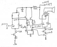
This one has 0.47u cap for AC coupling from the first gain stage to the CF stage. That is what I am talking about, this will be very easy. If you have to get rid of this cap, it is not going to be easy anymore. The gain of the first stage will cause drift because the DC is amplified by the gain of the first stage. I designed a complete DC coupled with CCS to try to control the current precisely. Problem is you still have the instability of the HT and sag of the HT upon large signal that affect the bias of the power tubes. Any change of the HT on the first stage change the bias of the power tube directly without attenuation at all. 2V droop on HT create 2V droop on the grid bias of the power tube.Here's a clever way to deal with grid current: 811A amplifier
An externally hosted image should be here but it was not working when we last tested it.
Only way is to have CCS for the power tubes, then the bias voltage is no longer critical. But you need large cap to bypass the cathodes of the power tubes!!! You have distortion right there. The only way is to follow Vacuum State using differential power tubes with CCS.
That's what I was asking about whether it's more critical to DC couple from first stage to the second stage ( CF) , or from second stage(CF) to the power tube. I think if I have to have a cap, it's better to do it before the CF.
Last edited:
I am not saying caps do not have distortion. The key from the other thread I linked is actually did the calculation how much the distortion really mean in a real life AC coupling situation. As you can see in post #15 there, the effect of the cap is negligible. If you read through the thread, you'll see. Even Mr. Merlin Blencowe agree to that for coupling caps as long as you use over sized value.
I would have no issue to use ceramic or electrolytic as long as I can use value that make the reactance <<< resistance of the RC network.
I would have no issue to use ceramic or electrolytic as long as I can use value that make the reactance <<< resistance of the RC network.
Problem is you still have the instability of the HT and sag of the HT upon large signal that affect the bias of the power tubes. Any change of the HT on the first stage change the bias of the power tube directly without attenuation at all. 2V droop on HT create 2V droop on the grid bias of the power tube.
Regulate B+ and bias.
Also, if your amp is fully differential with forced balance, the PSU simply doesn't matter anymore. I still regulate it anyway.
Most tubes (in the output position at least) seem to benefit from a source follower driving the grid. Some more that others. Recently I built a 6N16B balanced output stage, which really came alive after I added the source followers to the grids. It's a very low bias tube (-2V bias), and it seems to eat grid current even with no signal.
I've also done it DC. Works great, really transparent. B++ comes pretty high though. With strict (CCS tail) Class A, no drift can occur.
Likewise my 833C amps. Two stage, direct coupled, stable as a rock. Regulated bias supplies, gyrator/mu follower load on the driver tube which also acts as a source follower to supply grid current when needed (up to 200mA at times), regulated AC feeding the amp. Lots of ways to reliably skin this cat.
Only way is to have CCS for the power tubes, then the bias voltage is no longer critical. But you need large cap to bypass the cathodes of the power tubes!!! You have distortion right there. The only way is to follow Vacuum State using differential power tubes with CCS.
Yes, there are ways as I out lined in the last post. You regulate the current of the power tube that make the grid bias voltage moot. Also you can use DC servo, or like both you said, make everything precision and regulated.
The question is whether you actually have the identical circuit, just compare with or without coupling cap where the coupling cap is over valued. Is there any difference in the sound.
I am planning to use BJT with CCS emitter follower to buffer the LTP to drive the power tubes. I think BJT gives the least variation of the voltage ( Vbe is very constant ) compare to Vgs of MOSFET or Vgk of tube. So I won't add distortion. Both BJT and MOSFET do not have sudden input current conduction like triode. I think it's going to be fine to AC coupled from the LTP to the emitter follower. With that, I can design so the input is DC coupled to the LTP.
I am planning to try the differential power tube with CCS tail. If the $35,000 Vacuum State amp raved about this, that speaks louder than any theory.
here is one by Bob Danielak...dc coupled all the way....http://www.reocities.com/bobdanielak/technoteNo33.html
An externally hosted image should be here but it was not working when we last tested it.
I already have a rough design of the DC couple pp amp before I posted. Just question whether it is necessary as you can see the steps I have to go through to achieve that. I don't even use NFB, using emitter follower to drive the miller cap of the power tube to get wide band without NFB. -50V is rectified from the original -grid bias tap of the PT.
Attachments
Last edited:
- Status
- Not open for further replies.
- Home
- Amplifiers
- Tubes / Valves
- Why some people want DC coupling in power amp?