No, the 83 has two plates with a common filament. To make a hollow state FWB, you need VT diodes with independent cathodes, and all of these are small signal types, not large signal. Most of these FWB's use something like a 5U4GB, and two damper diodes with indirectly heated cathodes that need just one heater PTX between them.
Not very available (actually, rather obsolete), but a pair of PZ30 dual power rectifiers could be used, since they have separated anodes and cathodes. This valve is even rated in the data sheet for voltage doubler duty. The 52 volt heater is a bit awkward though. It was originally intended for TV use in a 300mA series heater chain.
For very low current (a few mA only) and moderate voltage the 6JU8 is an option and allows a small bridge rectifier in a single device.
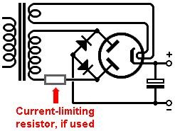
The main issue with a bridge rectifier made out of valves is that there are always two anode-cathode voltage drops in series which waste HT power from the transformer and contribute to poor voltage stability.
For very low current (a few mA only) and moderate voltage the 6JU8 is an option and allows a small bridge rectifier in a single device.
The main issue with a bridge rectifier made out of valves is that there are always two anode-cathode voltage drops in series which waste HT power from the transformer and contribute to poor voltage stability.
Reasons the electronics industry didn't use bridges:
- rectifier tubes are mildly expensive
- Centertapped secondaries on power transformers didn't cost that much more
- You'd have 2 tube rectifiers in series at any one time during the AC wave cycle, and you lose a lot of voltage inside a tube rectifier.
- easy to make a tube rectifier with two plates and one cathode, costs not much more than a single plate tube. A tube with one plate and two cathodes would be very expensive, and noone would buy them.
- Status
- This old topic is closed. If you want to reopen this topic, contact a moderator using the "Report Post" button.
- Home
- Amplifiers
- Tubes / Valves
- Bridge Rectifier with Fullwave Tube