Late edit:
The "diode'd" Mosfet uses an R divider (drain to source, tap feeding the gate), so is adjustable. Although I think two adjustments are needed, one for nominal resistance, and another for non-linear curvature. So the top divider resistor would be a pot, it adjusts the output V to I scale, or nominal resistance. A second pot under the Mosfet Source is used to degenerate the Mosfet non-linearity for curvature control.
Since this fixer-up tail would always be degenerating the output tubes to some extent to get leveled gm, one will want some extra gain available in the previous driver stage.
Last edited:
Any link to this DIY Nerdorama project?
http://www.diyaudio.com/forums/club...ver-island-diyfest-2014-a-21.html#post4028121
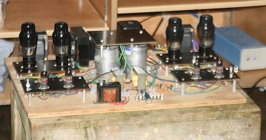
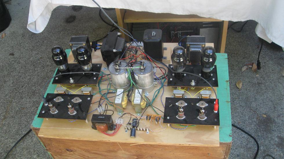
and a couple pictures:
dave
Picture certainly looks like it could be the 6AR6 circuit Jazbo8 posted, maybe with 6L6s installed and different drivers. Different interstage xfmrs too. Well maybe some iterations later.
----------------------------------------------------------------------------------------
The Keith-Snook info seems to find less need for R tail correction than the constant plate V curves would indicate. But he still ends up removing the cathode bypass caps. Not surprising that triodes would clean up some of the 3rd harmonic distortion via their internal feedback. But looks like tweeking the tail R can still help. Just cleaning up the 3rd H. dist. better before the feedbacks finish the job.
The (earlier, above) 6DR7 gm curves show the same gm curvature for all the plate voltages shown, so that curvature is still in there in some form. My further point was that they (gm versus Vg1) tend to straighten out at higher current, so the correction needs a little non-linearity too.
I don't don't think one is going to be able to calc. any R tail needed for something as subtle as distortion effects. The math or Spice models just aren't that precise. One needs a gain analyzer, or at least an FFT (soundcard) analyzer to tweak some dials. I think it really should be kinda fun to play with. Can always listen and see if you like it or not.
Last edited:
Picture certainly looks like it could be the 6AR6 circuit Jazbo8 posted, maybe with 6L6s installed and different drivers. Different interstage xfmrs too.
Why not just look at the schema John posted in the link and not guess?
dave
I'm still confused as to why Kiebert's paper says triodes and pentodes have a different 3rd order coefficient polarity. From looking at gm curves, it seems that either can have upward curvature, at least over part of their gm curve.
I am still reading and looking at your posts, it'll take me a while. I was reading about triode and penthodes, seems like both can be representing by power series:
y=a+bx+cx2+dx3
I use online math graphing and use y=5x+0.1x2+0.05x3+.002x4 for triode and y=5x+0.1x2-0.05x3+.002x4 for penthode
you can see the triode bend up and penthode bend down.
The point anyway was that just putting a CCS in the tail is not a magic cure all. Some finite impedance is more likely to give linearity. From looking at various gm curves like the Mosfet, when graphed versus gate V drive (Self, 4th ed. pg 502), the gm curve is a nice linear ramp. The derivative of square law V to I gives a linear ramp for gm. A power law above 2 gives an upward curving gm curve (on Vg base scale), and a 3/2 power law gives a downward trending curve. Since tubes are nominally 3/2 power law, but typically more like square law or above at low current due to grid/cathode wire proximity effects, their curves can vary in curvature. They get more toward a linear power law at high current, like Mosfets do. Cathode current saturation effects also round off the gm curve at the top.
My biggest problem in the articles is they are for triodes and the graph mandates that the plate voltage is constant. But we all know the transfer characteristics change when the plate voltage change in a triode. How valid is the conclusion and how well the harmonics really get cancelled out?
I am studying UL, seems like the UL can achieve lower distortion than triode. With good screen tapping, the 3 harmonics can be eliminated. According to one paper, 40% to 43% tap will be ideal for EL34 and 6L6.
Do you know how the sound comparison between differential power tubes with CCS tail vs good old grid bias with grounded cathode of the power tubes?
I have to take my time in studying on the others before responding.
Thanks
Last edited:
The UL tap can be chosen to eliminate the 3rd harmonic. And the UL scheme is helpful at putting the screen partitioned current back into the plate current (although only at 43% or so effectively). So it clearly has some significant advantage over just pentode mode. Since the triode will still have some 3rd H under load, it can look worse total distortion wise, but I suspect it may have somewhat lower higher harmonics. Whether anyone can tell much difference between them after global feedback, may be down to subtle subjective evaluation or FFT analysis. I think the differences there will get down to the actual tubes used.
One thing that bothers me about UL, is that the plate V swings way down below the screen grid, causing significant screen current effects. Some UL OTs provide an extra winding to lower the UL DC. A higher Z load causes more output voltage swing, and so more screen current effect. A lower Zload causes more g1 non-linearity to push the current. I suspect UL plays these (compressive versus expansive) distortions off against each other, and may only cancel 3rd H at one load Z. High screen current excursions are likely to put some higher order harmonics into the mix as well. Global feedback does tend to keep this all under control of course.
As to Kiebert's 3rd order C coefficient, I don't see where there would be any difference between a pentode with fixed Vg2, and a triode with fixed plate voltage, they are the same environment, except for maybe some small screen current effect. But that tends to be a constant factor when the Vg2 and Vp are held constant. I suspect his -C factor may be just down to the tubes he selected for analysis. Now maybe this is typical for audio type tubes, I don't know. But for later developed (higher gm) TV sweep tubes, I see the g1 power law consistently in the 2.0 to 2.8 region over a large current variation region. (6LQ6 is an exception at 1.9) So I would expect the gm curves of these to curve upward consistently. (well a straight ramp obtained at 2.0)
On the CCS tailed class A output stage, I was going to make a comment in the "The Differential Amplifier" thread. John_Tracy said:
"Another advantage of the LTP differential stage is in theory the output impedance is constant throughout the swing cycle."
Now Morgan Jone's book (pp 135,136 4th ed.) does say this is true for a balanced load output. Then he gives a derivation for the unbalanced case, but which indirectly shows that it is not the case for the balanced case either. On page 79, Jones gives Ra' = Ra+(Mu+1)*Rk for the unbypassed triode. Now when one triode in the CCS tailed output pair cuts off at max signal in class A, the Rk that it effectively provides for the other triode side goes to infinity (since it's gm goes to zero at zero current, 1/gm => effective Rk) So the other triode is then just sitting on a CCS tail, switched on, and the load Z does not have any back effect through the other triode. Zout goes to infinity.
So the CCS tailed triodes have a Zout varying between Ra||Rload at zero signal and infinity at max signal peaks. Need one say more?
Putting the optimum Rtail for 3rd harmonic null (assuming tubes with consistent >2.0 power law) in instead of the CCS will give a constant Rk and a constant total gm. Can't get any better than that for steady Zout. Now whether this sounds better, maybe not. I couldn't say.
Last edited:
Mr. Vaughn is obviously biasd in favor of SE, but there are some valid points he gave also.
Yes, he's a guru. Beware.
1) Can anyone give me link in the argument for PP over SE so I can hear the other side of the story? Anyone disagree with what he say and favor PP class A?
PP gives better utilization of the finals, regardless of whether you're talking RF amps or audio. For both, PP, being a balanced, two phase system is symmetrical, and can reproduce the whole signal cycle. That means you can drive the final to higher max currents than would be possible with Class A: the only choice if your SE amp is an audio amp.
In the RF case, PP complicates the output circuitry, and is not so adaptable to easy band switching. A Class C PP amp allows for the distribution of the total dissipation to be shared by two active devices instead of one.
PP also universally nulls all even order harmonics, so the output is cleaner.
2) In page 8 of the first paper, Mr. Vaughn claimed NFB kills the space and air between the instruments, parts and voices. Is that true?
It can be true. When I did the design for the Vixen, I ran it open loop. Lots of space, air, and an outstanding sound stage as well. Also just E-SSSS LOADS of all sorts of pentode nastiness. Lots of dissonant high order harmonics that were fingers on the black board nasty and hard to take for very long. NFB cleaned all that up, but at the expense of sound stage. There are almost always trade-offs that have to be considered: gain something here, give up something in exchange.
There seems to be a definite gray zone between just enough NFB to take the edge off, and amounts ~13dbv where everything begins sounding overly subdued and lifeless. You'll need even more to fix that, and such levels of NFB are beyond the capabilities of hollow state designs that use OPTs. There have been some heroic designs like the Williamson, but that one wouldn't work without some exceptional OPTs designed specifically for the task at hand. Otherwise, you will have stability issues, especially due to the phase misbehaviours of OPTs.
OTLs can use more NFB without the stability problems, and huge open loop gains are easy to come by with BJTs, so you can get the NFB "over the hump" and back into sound-good territory.
Bad circuits and bad devices make for bad sound, and abusing NFB to cover up for your open loop mistakes has given it a bad reputation.
3) In page 4 and 5 of the second paper, Mr. Vaughn explain in detail the B-H hysteresis, that SE has a big advantage over PP because in SE, the OPT core never goes through ZERO FLUX. So you don't have to worry about the hysteresis distortion. This seems to be a very big advantage to get a good OPT and keep a net DC current large enough to keep the OPT core from ever goes to zero flux during the operation. Is there any argument against this for PP?
It's nonsense. Just because you establish a steady state magnetization doesn't mean that the AC isn't still flipping domains. That still takes time and energy, so it doesn't make the hysteresis go away. It just translates it to another base line. It's an excuse in an attempt to turn a big negative into a positive, and it doesn't work. PP OPTs remain easier to design and construct for good sonic performance since you don't have to deal with core magnetization, and the impedances are frequently lower, and require fewer turns, less stray capacitance, less leakage inductance.
4) Follow up of question 3 above, how about using a CCS to always pull a current on one side of the PP OPT to keep the transformer from ever have to go to zero flux to avoid hysteresis. Yes, this means you have to have a bigger more expensive transformer that can take the DC current without getting into saturation. But its should be doable. Then you can have the high power of PP, but no disadvantage of distortion cause by hysteresis.
If this were a good idea, then manufacturers of OPTs would be including neodymium permanent magnets into their cores. It isn't, and they don't.
One thing that bothers me about UL, is that the plate V swings way down below the screen grid, causing significant screen current effects. Some UL OTs provide an extra winding to lower the UL DC. A higher Z load causes more output voltage swing, and so more screen current effect. A lower Zload causes more g1 non-linearity to push the current. I suspect UL plays these (compressive versus expansive) distortions off against each other, and may only cancel 3rd H at one load Z. High screen current excursions are likely to put some higher order harmonics into the mix as well. Global feedback does tend to keep this all under control of course.
Regarding to UL, I bet there is always a catch on everything. I did think about the plate can go lower than the screen on part of the cycle when the signal is large. BUT isn't it true for fixed screen voltage in pantode mode when you pull the screen to +HT? I always wonder about that. Even if the screen is biased 100V below the plate at idle, plate can still goes below the screen upon large signal. I don't see there is any disadvantage in UL in this respect.
One think I am confused, the articles I read all gave the optimized tap for EL34 and 6L6 are 40% to 43%. Why 33% is the most common with OT?
As to Kiebert's 3rd order C coefficient, I don't see where there would be any difference between a pentode with fixed Vg2, and a triode with fixed plate voltage, they are the same environment, except for maybe some small screen current effect. But that tends to be a constant factor when the Vg2 and Vp are held constant. I suspect his -C factor may be just down to the tubes he selected for analysis. Now maybe this is typical for audio type tubes, I don't know. But for later developed (higher gm) TV sweep tubes, I see the g1 power law consistently in the 2.0 to 2.8 region over a large current variation region. (6LQ6 is an exception at 1.9) So I would expect the gm curves of these to curve upward consistently. (well a straight ramp obtained at 2.0)
I read through most of the Kiebert's article that you posted, I didn't see what any of the pentode equation. This is the one on March 22-25, 1954. All the equation on page 26 to 27 are specified for triode mode ONLY. I don't follow what you said. Do you have another of the Kiebert article on this?
For the polarity of the coef of x3 term, I just read some article about the bending of the curve and use the power series to experiment only. Do you have any article that give more on the power series representation of triode and pentodes?
On the CCS tailed class A output stage, I was going to make a comment in the "The Differential Amplifier" thread. John_Tracy said:
"Another advantage of the LTP differential stage is in theory the output impedance is constant throughout the swing cycle."
Now Morgan Jone's book (pp 135,136 4th ed.) does say this is true for a balanced load output. Then he gives a derivation for the unbalanced case, but which indirectly shows that it is not the case for the balanced case either. On page 79, Jones gives Ra' = Ra+(Mu+1)*Rk for the unbypassed triode. Now when one triode in the CCS tailed output pair cuts off at max signal in class A, the Rk that it effectively provides for the other triode side goes to infinity (since it's gm goes to zero at zero current, 1/gm => effective Rk) So the other triode is then just sitting on a CCS tail, switched on, and the load Z does not have any back effect through the other triode. Zout goes to infinity. So the CCS tailed triodes have a Zout varying between Ra||Rload at zero signal and infinity at max signal peaks. Need one say more?
I think the differential output stage is meant ONLY for Class A operation. When one tube turns off, the other tube cannot conduct any extra current as the current is constant governed by the CCS tail. The signal clips at that point. Yes, the output impedance goes high, but that should not matter as the signal clips already.
Putting the optimum Rtail for 3rd harmonic null (assuming tubes with consistent >2.0 power law) in instead of the CCS will give a constant Rk and a constant total gm. Can't get any better than that for steady Zout. Now whether this sounds better, maybe not. I couldn't say.
Thanks for you detail reply
I still yet to finish reading some of the articles you gave, it's a lot of reading. Articles on tubes are usually not well written and I have to second guess a lot of the things.
Also, it's very hard to decide whether to go differential output stage or go simple grid bias with grounded cathode. Main thing is the heat dissipation. I use it at home, the differential output stage has to run in Class A. That will be very hot. For simple grid bias, I can run in Class AB1 with the first 3 to 5W in Class A where most of the program plays. I kind of resist in building a low power Class A amp even though logic tells me I don't need anything more than 5 to 10W at all.
Merry Christmas
Last edited:
On Kiebert's paper, I was referring to the bottom of page 26 (2nd page), where a Note appears:
(Note that the sign of ce1^3 and ce2^3 is plus for triodes) (and minus for pentodes)
So he apparently concludes the Rtail scheme will only work for triodes from there on out. But looking at the 10JA5 datasheet, page 5 (one of the few output tube datasheets with gm curves) one can see that it does curve upwards over most of the range. Apparently it must have a positive C 3rd order factor.
http://frank.pocnet.net/sheets/123/1/10JA5.pdf
Or looking at 12HE7, a horiz. sweep tube, with no gm curves provided. Using the plate curves on page 3 to tabulate some g1 driven plate currents at 200 Vp:
(-39Vg1 is taken as the zero current point, so for effective Vg1 for power law curve derivation: -25V=> 14V, -20V=>19V, -15V=>24V, -10V=>29V, -5V=>34V,0V=>39V)
14V 38mA
19V 87mA
24V 157mA
29V 268mA
34V 392mA
39V 527mA
Then using every other data point to solve: (V'/V)^n =I'/I
one gets n = 2.63,2.66,2.63
A very consistent power law over the full current range. I am surprised at how steady it holds up for g1 drive.
One can do the same procedure for the g2 driven plate curves on page 4 and one gets n = 1.23,1.22,,1.24
Very consistent again, and that is expected. I would have expected more like a 1.5 power law, but it seems that many screen grids operate below that magic number.
21HB5 has almost identical curves to the 12HE7. (I think 12HE7 is just a cut down plate to fit in the same bottle with the damper section.)
So it would seem that a fixed R tail could be used with these tubes since the g1 power law is consistently above 2.0. Similar results show up on many other TV sweep tubes. I need to get a table of these results together some time..... I've mainly analyzed the cheap $1 sweep tubes I got a few years ago. But I should work up the whole bunch of Sweep types. Looks to me like these el-cheapo TV tubes can do better than a 300B when in triode config., class A, and with an appropriate R tail. The usual assessment is that the TV sweeps are less linear that the "golden" tubes, and that is certainly true without the fixup R tail, but these may be the "goto" tubes for greater than 2.0 power law, R tail, fixup.
-------------------
Another point on the UL setup, the compressive screen current effect is plate V driven, while the expansive g1 gm effect is plate current driven. While these can be balanced for a given load Z, they go out of phase if the load is reactive. That can't be too good. You will find comments on the sound of UL all over the map, so this probably all depends on the tube used. It also points in the direction of low Vg2 tubes with a DC voltage dropper from the UL tap. Using an oversize TV sweep can allow rather low Vg2, keeping screen current effects at bay.
-------------------
It's not just when the one triode actually cuts off in the P-P triode, class A, CCS tail configuration when Zout soars. Gm is varying with signal and smoothly dips to zero at signal peaks. So the Zout is varying all over the place there. One should probably do a simulation/analysis to find out just how much of a problem there is. It's not an issue in resistor loaded gain stages fortunately.
-------------------
I have an equal aversion to class A, its just that it works so darn much cleaner in a simple setup.
Some people have a class A amp just for winter. I do however think that class AB can be made to work well without too much trouble, and if one is willing to go to extra effort with clever correction schemes, one might equal class A.
Last edited:


Ha ha, actually SE is more common in RF, they don't necessary run in Class A, more likely class C.the only choice if your SE amp is an audio amp.
Can you explain what is the meaning of say 20dB feedback? Does this mean 20dB( gain of 10) closed loop gain? I don't know the naming. Far as I know, it's the loop gain (open loop gain minus closed loop gain in dB) that makes the difference. This control how much reduction of distortion, reduction of output impedance you can get. If the loop gain is high, the lower output impedance you can get.When I did the design for the Vixen, I ran it open loop. Lots of space, air, and an outstanding sound stage as well. Also just E-SSSS LOADS of all sorts of pentode nastiness. Lots of dissonant high order harmonics that were fingers on the black board nasty and hard to take for very long. NFB cleaned all that up, but at the expense of sound stage. There are almost always trade-offs that have to be considered: gain something here, give up something in exchange.
It's nonsense. Just because you establish a steady state magnetization doesn't mean that the AC isn't still flipping domains. That still takes time and energy, so it doesn't make the hysteresis go away. It just translates it to another base line. It's an excuse in an attempt to turn a big negative into a positive, and it doesn't work. PP OPTs remain easier to design and construct for good sonic performance since you don't have to deal with core magnetization, and the impedances are frequently lower, and require fewer turns, less stray capacitance, less leakage inductance.
I figure that much!!!
I definitely want more open and more the sweetness sound. That's the reason my first draft has no NFB. The second draft have NFB, but the loop gain is very low. I only have the LTP driving the power tubes. The LTP has gain of about 50, the power tubes to the secondary of the OPT is unity gain at best. So the open loop gain is only 50. If I do a closed loop gain of 10 ( is this 20dB feedback?), I only have loop gain of 5 or 15dB. So it's only going to lower the output impedance a little bit. Just a little compensation over the one with no NFB.
Let me know what you think.
Merry Christmas
Alan
Can you explain what is the meaning of say 20dB feedback? Does this mean 20dB( gain of 10) closed loop gain? I don't know the naming. Far as I know, it's the loop gain (open loop gain minus closed loop gain in dB) that makes the difference. This control how much reduction of distortion, reduction of output impedance you can get. If the loop gain is high, the lower output impedance you can get.
The feedback formula is:
20log(Avol/Avcl)= 20log(1 + B*Avol) where these are logarithms to the base of 10.
I definitely want more open and more the sweetness sound. That's the reason my first draft has no NFB. The second draft have NFB, but the loop gain is very low. I only have the LTP driving the power tubes. The LTP has gain of about 50, the power tubes to the secondary of the OPT is unity gain at best. So the open loop gain is only 50. If I do a closed loop gain of 10 ( is this 20dB feedback?), I only have loop gain of 5 or 15dB. So it's only going to lower the output impedance a little bit. Just a little compensation over the one with no NFB.
Basically, what you want is a Doug Self Niceness Knob. There are ways to do that: you can make the NFB variable. I've done that. You can also add imbalance to the phase splitter to add back in the h2 you lost when implementing the balanced design. Here's a phase splitter that can do that, and you can add a twiddle knob to the panel.
The Van Scoyoc splitter also can be unbalanced.
Other than that, you can go SE throughout, not connect in any NFB, and place yourself at the mercy of your active and passive devices. Therein lies the way to rolling tubes, capacitors, resistors, magic speaker cables and power cords, and the Magic Stones, and the miracle paints and goops, and so on, and so on, and on and on...
Merry Christmas
Alan
And a Merry Christmas to you too.
Attachments
- Status
- Not open for further replies.
- Home
- Amplifiers
- Tubes / Valves
- Question and comments on SE vs PP by Eddie Vaughn