Hi all,
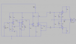
I'd like your opinions on how to improve on the following schematic. I've put everything together from what I learned and found in the past few years.
For my speakers I only need about 1 watt, so that's why I'd go for triode, maybe a switch to UL or Pentode mode would be nice.
I'm trying to build for the lowest THD possible...
So I'd like some help with the feedback and maybe if necessary a css for the phase inverter.
i've attached the ltSpice files for you to play with.
thanks for your help!
Attachments
Anyone? I've found the following thread but the schematics are missing...http://www.diyaudio.com/forums/tubes-valves/127590-807-tube-triode-connected-2.html
What SY said, but more than that this is probably a step backwards from the old Mullard 5-20 topology which is readily adaptable to this application using a 12AX7 based front end. (Note that if you are not using global feedback an even lower mu triode in the front end is a good idea - way too much gain otherwise)
I don't use global feedback in any of my new designs, but you do pay a penalty in much higher source impedance and without considerable care in design on the distortion front as well.
Finally I would choose something other than the 12AU7A for phase splitting.. Consider the 6CG7/6FQ7, 6SN7 or even the 12AT7 (not the most linear, but since it is mostly 2nd harmonic it will cancel in PP)
12AT7 (not the most linear, but since it is mostly 2nd harmonic it will cancel in PP)
Actually, quite a bit more linear than 12AU7. And as you implied, much lower odd order distortion.
Hi all,
I'd like your opinions on how to improve on the following schematic. I've put everything together from what I learned and found in the past few years.
For my speakers I only need about 1 watt, so that's why I'd go for triode, maybe a switch to UL or Pentode mode would be nice.
I'm trying to build for the lowest THD possible...
So I'd like some help with the feedback and maybe if necessary a css for the phase inverter.
i've attached the ltSpice files for you to play with.
thanks for your help!
I think the 12AU7 LTP does a better job with UL or pentode output stage. It is not bad as many people say however I would never use 1M resistor on the grid of output tubes. No need of ccs. You do need a good OT for applying feedback without too many troubles.
Have a look at this:
http://www.tube-amps.net/images/KT88_PP_01/KT88_Schematic.jpg
Hashimoto KT-88 UL Push Pull
I think the rising distortion (but still equal or less than 0.04% up to 5W Pout) at very low output level in the EL34 amp is mostly due to the choice of running the EL34's in class B.
In your case, as you don't need too much power you could run the 6bg6 as from data-sheet with 250V on both plate and G2 and approx. -15V bias for 70-75 mA plate current. With 5K plate-to-plate which is easy to find you might get some 12-15W in pure class A in pentode mode.
In your case, as you don't need too much power you could run the 6bg6 as from data-sheet with 250V on both plate and G2 and approx. -15V bias for 70-75 mA plate current. With 5K plate-to-plate which is easy to find you might get some 12-15W in pure class A in pentode mode.
There was a discussing some little time ago about including the OT in the global feedback loop vs keeping it out. The general feeling I took form it was that if the finals are in the feedback loop but the OT is not included - the finals will have a lower output impedance which will drive the OT better and produce less distortion overall. Including the OT in the design in the feedback loop introduces phase issues which can introduce instability and rarely corrects the imperfections of the OT satisfactorily. Driving the OT with a lower impedance means all its parasitics have less effect and the frequency response open loop is better overall than with a poor drive to those parasitics from a higher impedance source, which is what you get when the feedback is after the OT vs from the finals.
As a personal choice I would never include the OT in a global feedback loop, but also I would tend to work with local feedbacks to make each stage more intrinsically linear. Correcting cumulative errors after going through multiple amplification/transformation stages is prone to generate more complex distortion components.
Shoog
Hi all,
I'd like your opinions on how to improve on the following schematic. I've put everything together from what I learned and found in the past few years...
I'm trying to build for the lowest THD possible...
You have used LTspice but why haven't you noticed that your LTP-phase inverter does not work well ? There is no proper biasing and the balance is also vey poor.
The front end amplifier with two 12AX7 works perfectly as well as the output stage.
But just one 12AU7 halve can replace it if you want to make the circuit more simple. The performance will remain the same as now.
I have attached the modified circuit for you.
The main features are printed on the schematic.
(Pout = 5.5 W, THD = 0.33 %, Output impedance = 1.1 ohms, Sensitivity = 0.26 Vrms).
In case you look for even lower THD you can apply some 6...10 dB GNFB without any concern about instability problems.
Attachments
I think the rising distortion (but still equal or less than 0.04% up to 5W Pout) at very low output level in the EL34 amp is mostly due to the choice of running the EL34's in class B.
In your case, as you don't need too much power you could run the 6bg6 as from data-sheet with 250V on both plate and G2 and approx. -15V bias for 70-75 mA plate current. With 5K plate-to-plate which is easy to find you might get some 12-15W in pure class A in pentode mode.
that is music to my ears, 0.04%
 but after two weeks of messing with LTSpice, I just can't seem to get this to work at all. probably has something to do with the ef86.
I also like the idea of the minus bias voltage, I do have a spare winding on my power transformer 100v have to lookup its ampere rating. so maybe just add another transformer.
You have used LTspice but why haven't you noticed that your LTP-phase inverter does not work well ? There is no proper biasing and the balance is also vey poor.
well as you might have noticed I build this first schematic after only a hour of working with spice. On top of that this was my first try ever building something myself.
Thanks for adjusting the schematic, I learned some nice new stuff on the LTspice program
then again, still haven't found how to measure the THD.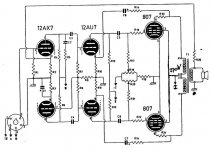
This is the hv-214 from an old Dutch magazine Radio Bulletin
Hoi Jaap, do you have any specs or info with that schematisch?
Hoi Jaap, do you have any specs or info with that schematisch?
Here is some more info, perhaps the old guys at this Dutch forum can provide you with the magazine article Nederlands Forum over Oude Radio's
Attachments
Hi all,
I'd like your opinions on how to improve on the following schematic. I've put everything together from what I learned and found in the past few years.
For my speakers I only need about 1 watt, so that's why I'd go for triode, maybe a switch to UL or Pentode mode would be nice.
I'm trying to build for the lowest THD possible...
So I'd like some help with the feedback and maybe if necessary a css for the phase inverter.
i've attached the ltSpice files for you to play with.
thanks for your help!
Why use the 12AX7 to make an independent gain stage with gNFB? Secondly, the design is hideous. The 12AX7 has an rp= 90K (nominal) and a 56K load is way too heavy here. That's gonna make a helluvalot of distortion. That's the big mistake people make with 12AX7s: plate loads that are way too small, and then they complain about the 12AX7's sonic performance. If you don't have the voltage for a proper sized passive plate load, then you should go with an active plate load.
The gNFB will correct for that, but it's always better to make the open loop as free of distortion as you can, then improve it with gNFB. You don't want to be using gNFB to cover up a bad open loop design. That's how NFB got a bad rep in the first place.
It would be much better to use the 12AX7 as an LTP/splitter 1st pre DC coupled to the 12AU7 differential. You can use an active tail load for the 12AX7, and a passive tail load for the 2nd pre, since it's already receiving a balanced input. Even better would be to use a 6FQ7 as the second balanced pre, and the 12AU7 as a cathode follower grid driver, especially if you're using the 6L6-oid as a triode. If you don't want the extra hole in the chassis, then a MOSFET source follower will serve just as nicely as a grid driver. It also has the advantage of getting those capacitors out of the final's grid circuit and the blocking distortion that a clip can cause.
I've actually been looking for a good schematic for 6bg6 tubes as well. I picked up a nos set of 4 at a ham fest last year, now I'm ready to use them. I did fine one on a French tube site. I will post the link for you this weekend.
Allow me: The Vixen
- Status
- This old topic is closed. If you want to reopen this topic, contact a moderator using the "Report Post" button.
- Home
- Amplifiers
- Tubes / Valves
- comments/corrections on 6bg6 pp triode amp