I was reading this thread and it got me thinking about what a blameless tube amp might look like. The Aleph CCS, when used properly, dramatically improves performance of SS amps (ie. Aleph, Zen). Has anyone out there modified the Aleph CCS to work in a tube amplifier? If so could you tell us about it? If not, is there a reason this couldn't work?
I kind of disagree that there is anything special about the aleph ccs. However, I have built a preamp with a cascade mosfet ccs, and it's fine. I doubt you could distinguish between bipolar or mosfet ccs's in a tube amp without test equipment.
Leadbelly take a look at how much the Aleph CCS improves the performance of the Zen . The distortion is 10X lower on the aleph CCS circuit.
I kind of disagree that there is anything special about the aleph ccs. However, I have built a preamp with a cascade mosfet ccs, and it's fine. I doubt you could distinguish between bipolar or mosfet ccs's in a tube amp without test equipment.
I made a circuit that allowed me to switch between a cascade bipolar CCS and a cascade MOSfet CCS load in a headphone amp - the difference was not even subtle!
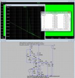
Here is an attempt...
1626 tube at 111V on the plate and 8V on the cathode for 15mA through the tube. Had to play with the values of R5, R6, and R7 to get the correct bias current and a decent enough frequency response (roughly within 0.5dB from 20Hz to 80kHz). Not the greatest of results, but 0.4%THD out of a 1626 isn't too bad.
1626 tube at 111V on the plate and 8V on the cathode for 15mA through the tube. Had to play with the values of R5, R6, and R7 to get the correct bias current and a decent enough frequency response (roughly within 0.5dB from 20Hz to 80kHz). Not the greatest of results, but 0.4%THD out of a 1626 isn't too bad.
Attachments
I made a circuit that allowed me to switch between a cascade bipolar CCS and a cascade MOSfet CCS load in a headphone amp - the difference was not even subtle!
I am not doubting your result but are you sure, the MOSFFETs did not oscillate? (this question is meant seriously). Some of them can be quite hard to tame..
That would easily explain dramatic differences in perceived sound.
Otherwise, the cascade MOSFET CCS should be close to an ideal CCS on paper.
I am thinking along the line of a depletion mosfet-based CCS like 01N100 + DN2540, etc.
IMLE, they perform flawless without any "coloration of the sound", except lower distortion and higher amplification factor compared to a resistor load.
My bipolar CCSs that I used before often performed worse (lower R), but did not change too much in circuit performance, but YMMV.
Best,
Martin
Hi,
Yes, I'm sure they did not oscillate. I clip the gate lead of the MOSfet and solder an inline ferrite bead, plus a gate stopper R right next to it on the PCB (100R seems to be enough).
The MOSfet CCS was made with 01N100 + DN2540 indeed, the bipolar with BC560+MPSA92, LED biased.
I have measured their respective impedances, there is a whole discussion about this somewhere around the forum here. The MOSfet CCS performed much much better.
The MOSfet load gave a noticeably wider sound stage, the bipolar load sound was more "in my head" (I used Sennheiser HD650 headphones for the test).
OK, that makes some sense (at least to me).
I misunderstood your post (Sorry about that). I actually thought, you meant the other way around (that the bipolar one was better).
IMLE, the cascaded mosfet version really is close to an ideal anode load (I like the 01N100 + DN2540 combination, too).
I can see (at least on paper) why there can be an improvement in performance (especially when listening carefully with headphones)
Martin
Here is an attempt...
1626 tube at 111V on the plate and 8V on the cathode for 15mA through the tube. Had to play with the values of R5, R6, and R7 to get the correct bias current and a decent enough frequency response (roughly within 0.5dB from 20Hz to 80kHz). Not the greatest of results, but 0.4%THD out of a 1626 isn't too bad.
Unfortunately there is a huge mistake in this implementation.. Think for a moment what C1 is doing here and what is the overall load impedance reflected to the plate. (Hint it's not what you think.)

At what output level (I'm guesing about 1.2Vrms)? Since the valve appears to be driving a 5k load (not to mention R3), I don't see what use the CCS is, unless you're stuck with a low supply voltage or something?but 0.4%THD out of a 1626 isn't too bad.
Last edited:
I also wanted to ask this a long time to do so.The Aleph CCS, when used properly, dramatically improves performance of SS amps (ie. Aleph, Zen). Has anyone out there modified the Aleph CCS to work in a tube amplifier?
But what's even more interest is tho use the Nelspn Pass X supersymmetric circuit in tube amplifiers!!!
- Status
- This old topic is closed. If you want to reopen this topic, contact a moderator using the "Report Post" button.
- Home
- Amplifiers
- Tubes / Valves
- Has anyone tried the Aleph CCS in a tube amp?