Is it possible to parallel tubes? This was a post to find older posts. But nothing came up. I would like to drive a SE 6550 using 6CG7. I was wondering if you could use the triode halves in paralell using a common plate resistor and a common cathode resistor? Would it be a bad idea?
Yes, even when I was six I asked a million questions.
Kevin
Yes, even when I was six I asked a million questions.
Kevin
Last edited:
Is it possible to parallel tubes
Sure, with separate cathode resistors.
With parallel power tubes, the modes for HF or VHF parasitic oscillation abound. This is usually easily dealt with though. Feed paralleled screens via individual screen stopper resistors installed right at the sockets. A few hundred ohms is typical. In stubborn cases connect to anodes via chokes in parallel with resistors like transmitter practice.
Resistors in series with the control grid should ALWAYS be installed individually for each paralleled tube.
If you don't have a CRO with which to detect HF or VHF oscillation, parasitic oscillation shows up as unexpectedly bad distortion much worse than the circuit should provide. If the distortion gets noticeably worse or better with a plastic coated meatl plate brought near the tube or tube socket in question, you've got parasitic oscillation. Or you can use a scanner radio to pick it up.
If you are not talking about power tubes, but small triodes in driver stages or preamps (eg 12AU7, 6CG7) there should be no problem, as their gm is low - paralleling with common load resistors is often done. It's ok to use a common cathode bias resistor if the two triodes are in the same twin triode.
Last edited:
Since the tubes are connected in parallel the plate voltage of course will be the same, what is important is that the plate current is the same.
Some provision for adjusting grid bias independently in output stages is a good idea, in voltage amplifier circuits cathode resistors should be kept separate.
I've designed and built phono stages with many 12AX7A in parallel. (Use a single D3A or similar instead!) Independent cathode resistors works best.
I built a small run of PPP power amps in the late 1990s, and relied on good matching in the parallel pairs rather than making the bias independent, this has worked fine but requires well matched tubes.
Is it possible to parallel tubes? This was a post to find older posts. But nothing came up. I would like to drive a SE 6550 using 6CG7. I was wondering if you could use the triode halves in paralell using a common plate resistor and a common cathode resistor?
Kevin
Are you just trying to double the amplification factor from 20 to 40 in a mono amp?
Last edited:
Are you just trying to double the amplification factor from 20 to 40 in a mono amp?
Tubes in parallel will not exceed the mu of a single tube, however rp will be halved, transconductance doubled, and internally generated noise will be about 3dB less.
I would still use separate cathode resistors in the proposed 6CG7 based driver. (You can bypass the cathode resistors individually if needed)
What about 6J6, or 6SC7, difficult to use separate cathode resistors on those.
6J6 is recommended to use as a PP signal tube, but would be interesting to use in a Schmidt type phase splitter.
And, yes - use separate grid resistors on powertubes - really cools those oscillations down.

Using a pair of Peavey 50/50 ´s as HiFi poweramp´s - thats 4+4 6P14P-EV and 2 output transformers in paralell per side.
6J6 is recommended to use as a PP signal tube, but would be interesting to use in a Schmidt type phase splitter.
And, yes - use separate grid resistors on powertubes - really cools those oscillations down.

Using a pair of Peavey 50/50 ´s as HiFi poweramp´s - thats 4+4 6P14P-EV and 2 output transformers in paralell per side.
may be not in all cases - go to post #2 aboutSure, with separate cathode resistors.
http://www.diyaudio.com/forums/tube...de-without-cathode-resistors.html#post4146003
check out also this papers:
http://www.tubecad.com/articles_2002/RIAA_Preamps_Part_2/page2.html
http://www.tubecad.com/october99/page16.html
Last edited:
may be not in all cases - go to post #2 about http://www.diyaudio.com/forums/tubes-valves/265620-6922-e88cc-parallel-mode-without-cathode-resistors.html#post4146003
Yes, matching and selection is better, but as the tubes age they can drift apart, even the two sections of a dual triode in the same envelope.
What about 6J6, or 6SC7, difficult to use separate cathode resistors on those.
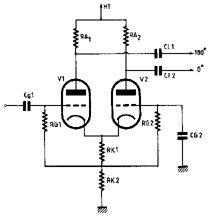
would be interesting to use in a Schmidt type phase splitter.
These would lend themselves to being used in long tailed pair circuits. And googled "Schmidt phase splitter" and I see it looks like a variant of the long tailed pair.

I suppose you could replace RK2 with a constant current source.
- Status
- This old topic is closed. If you want to reopen this topic, contact a moderator using the "Report Post" button.
- Home
- Amplifiers
- Tubes / Valves
- parallel tubes
