Built Currawong
I have built one but can't give you a critical appraisal due to an unacceptable level of motor-boating noise from both channels.
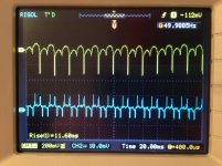
The attached image shows +HT and one output.
The spikes in the output look to be +/-10mv. The ~200mV spikes in the HT could be a concern.
Still trying to track down the source.
I have built one but can't give you a critical appraisal due to an unacceptable level of motor-boating noise from both channels.
The attached image shows +HT and one output.
The spikes in the output look to be +/-10mv. The ~200mV spikes in the HT could be a concern.
Still trying to track down the source.
Attachments
Only partially. I found that if I ran the amp with the board out the front of the plinth there was no hum. As soon as I slid it back into its slot the hum returned.
Redressing all the wiring to make it exactly the same as in the picture made no difference.
So I put a thin sheet of earthed steel between the transformers and the board and that improved things somewhat in one channel but made little difference to the other. Eventually I'll try enclosing the transformers but the amp is an expensive ornament at the moment.
Ohoh, there as a Currawong thread in here.
I have built one myself, but I managed to mix the NPN with the PNP-transistors so the HV PSU never "started". Will whenever I have the courage, time, energy solder new transistors in place of the misplaced of the wrong ones.
Even though I have spent some money on this project, my expectations aren't that mile high. From what I have seen from other tube projects published in the Australian magazine Silicon Chip, I am not really impressed.
However the Currawong seemed to be a fun project, using (cheap) 6L6, cheap transformers and (sadly) too much logic and control circuitry. Another "plus" is the conservative use of the 6L6. Getting just some poor 10/channel must mean that the tubes are driven very ecologically and the life-time ought to be loooong. But never the less, a sort of fun project, suitable for some tube rolling. I got a bunch of Chinese 6L6, Russian 6P3S-E and I just laid my hands on a quad CV1075 NOS. Being home all alone this X-mas could give me some spare moments to do the final soldering.
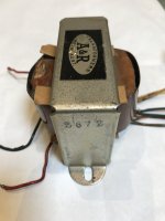
A&R 2672
Can you give me some information/specs on the A&R 2672. I have one but can't find any info? Cheers
That is coz it is A&R Tranny. <snip>
Can you give me some information/specs on the A&R 2672. I have one but can't find any info? Cheers
Can anyone provide any insight to how the currawong would perform compared to say an elekit tu8200, I feel like the cost of building the plinth for the currawong "as described in silicon chip" would bring the currawong into the elekit price range, trying to decide what one to pull the trigger on.
Regards Chris
Regards Chris
Last edited:
I realise it seems a bit chalk and cheese, I only ask the question because they are of similar power output , 10watts vs 8 seems close enough to disregard the advantage of a push pull design. More to the point I want to build something but I want a starting point. Eg a kit I can modify and make my own and these 2 are on the cards due to price point and availability
I bought a pair of Hammond 125E for another project (6V6-PP), just to find I had a pair of Chinese transformers already. So I simply came up with the idea of using the Hammonds in the Currawong.
But first have to deal with some serious issues, like why it blows fuses and when it doesn't why don't I have a HV on the anodes???
If nothing helps, I will propably through out the silicon stuff.
But first have to deal with some serious issues, like why it blows fuses and when it doesn't why don't I have a HV on the anodes???
If nothing helps, I will propably through out the silicon stuff.
My OPT is a 2672, which doesn't appear to be listed in the Ferguson Cat. It was sold as belonging to a cannibalised playmaster. Maybe I got duped
I have an A&R 2672 transformer. I don't have the specifications and don't know the colour codes. I've done some turns ratio calculations and I can get around 3.75K to 16 ohms using the green - orange secondaries. Do you need it- I bought it as a used component? Cheers
Would you have the specs for an A&R 2672 transformer? I have a used one but can't make out the specs - can't find it listed in the A&R catalogue!That is coz it is A&R Tranny.
Keep going down that linked page and you will get to the A&R pages. You did'nt get duped.
It seems like Keit's linked source is doing A&R copies but I did'nt like the prices.
Probably cheaper to grab some ST35 Trannies from the States or buy Hammond 1608 (8K Raa) or 1609 (10K Raa). I've used both of these Hammond trannies and was quite satisfied with their quality. Seen good reports of the ST35 trannies but never tried one.
Will also check to see if I have an A&R 2672.
Off the air for next few days, or possibly only one, NBN installed my fibre modem and battery backup inside my house 2 weeks ago and Telstra come tomorrow to fit my router/WiFi Modem and change my land line phone connection to work on the NBN fibre. New Dell Laptop turned up yesterday so about to join the 21st century at home rather than relying on work facilities.
Cheers,
Ian
Definitely 2672. Primary Red, Black (CT) Red. Secondary Yellow, Yellow, Blue, Green, Orange, Grey. About the same size as a Rola B29 O/P (10K P-P to 15 ohms) around 10 watts.Hi Bernhard,
2672 or 2627?
Attachments
Im wondering if anyone has built one and got it working, i recently bought one and im only getting 180v between d1 and ground while the manual says i should be seeing around 330. slowly diagnosing it but i havent found anything obviously wrong,
my next step will be to buy a new schmitt and transistors and replace all of them.
my next step will be to buy a new schmitt and transistors and replace all of them.
I was never able to get a hum/buzz in both channels out of mine and eventually scrapped it. Getting the PCB in and out was a real PITA. It was my first foray into valve amps and I've built quite a few successfully from scratch since.
I've no idea what experience you have working with high voltages so some words of advice. The designer of this amp very wisely included the blue LEDs/resistor string to indicate when high voltages are present and discharge the power supply capacitors when the amp is turned off. I do that in all my amps.
When I'm doing measurements I usually attach clips with the amp off and the power supply caps discharged. I turn the amp on, do the measurements, turn it off and move the clips for the next measurement. I don't like moving probes/clips around inside a live amp but if you do, make the earth probe/lead a clip and leave it in place while you move the other probe around taking measurements with one arm, with the other arm permanently behind your back.
Anyway, troubleshooting is complicated by everything being on the one PCB so you can't disconnect things. Are you measuring 180V with the valves in place? If so, remove all the valves and measure again. If the voltage is OK, turn it off and put the 12AX7s back in, turn it on and measure again. If still OK, put the left channel output valves back in and measure again. etc.
You should also check that there's ~114VAC across pins 1 and 3 of CON7. The socket itself is under the PCB but the 3 pins are accessible from the top of the PCB.
You can always contact Silicon Chip too. They're very happy to offer advice usually quite promptly, but the exchange could get published in the magazine.
i will just give the initial warning that this was my first introduction to HI-FI.
but plugging from the 3.5mm jack of my computer to the rca should be a good enough input for this device correct?
across pin 1 and 3 of CON 7 i am seeing ~132v ac (which correlates the the 186 volts that im seeing from d1)
i also notice im seeing 14.3v ac across the pin 1 and pin 3 of CON 8 (12.6v silkscreen) aswell as 14.3v across pins 4 and 5 of CON 8
all the voltages iom reading are around 15-20% out which i think is quite significant.
Edit:
i also just tested it with dinkle connectors disconnected so there is no way the caps can be influencing it, and they are reading the same values. so im thinking i either wired the toroidal transformer wrong or its faulty.
Your computer audio output should be fine. I thought the amp was once working but now isn't. If you've assembled it yourself the transformer could indeed be wired incorrectly.
The original design had 2 transformers wired in series. If the second transformer wasn't connected with the correct polarity, you wouldn't get the full voltage. As I recall, a single transformer was introduced later but I can't find any information on that.
The original design had 2 transformers wired in series. If the second transformer wasn't connected with the correct polarity, you wouldn't get the full voltage. As I recall, a single transformer was introduced later but I can't find any information on that.
- Home
- Amplifiers
- Tubes / Valves
- Silicon Chip mag "Currawong" amp