Hi- I thought I should post what Jack said about this question and about the circuit in general :
We indicated a 100ma primary when we thought you were talking about a SE 300B type transformer which is a 100ma primary, later you told us it was a
p-p. P-P's have two primaries, designated as a 100/100ma primary. No problem on these.
The primary/s current peaks are just that, peaks, the wire size is usually decided on as 70% of peak current. So since you did not, or do not know,
the real peak current, we assume that the 100/100ma should work fine."
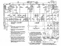
"We never seen this one, but typical Western Electric engineering. We do know it’s capable of about 30 watts or less and was for a small theater maybe and is made for the standard limited bandwidth. It is a good circuit for its original use, it is not full bandwidth.
As for the NFB, there are three NFB positions, R3, is unbypassed, C9/R15 and C8/R14 are NFB loops. This is to control natural distortion of beam power tubes. Also, Yes!! You are right, they do not start loop from output secondary so output trans is not affected so all is fine with this transformer.
This is a very tight circuit so pay attention to voltages and resistor values on this. The parts controlling the highs are C7, C11, C12. R12 is an intermodulation distortion null adjustment, (IMD) and will need special equipment to adjust. You will need, at least, a Distortion analyzer (THD) to get all values correct as well as null. These were not production types like the other major brands in those days, each was most likely tuned to work with the combined chassis parts used. Your removal of some caps for increasing bandwidth on the highs, my alter other things. This is a serious project and test equipment will be needed to see if all works right."
I hope I am not in over my head. I will build it and have an expert help me tune R12 and pray that it sounds good. I don't like what he says about the circuit not being "full bandwidth" I assume he is speaking not only about the limited frequencies of the 171C output trans. but about the circuit in general. Does anyone have any comments on this?
We indicated a 100ma primary when we thought you were talking about a SE 300B type transformer which is a 100ma primary, later you told us it was a
p-p. P-P's have two primaries, designated as a 100/100ma primary. No problem on these.
The primary/s current peaks are just that, peaks, the wire size is usually decided on as 70% of peak current. So since you did not, or do not know,
the real peak current, we assume that the 100/100ma should work fine."
"We never seen this one, but typical Western Electric engineering. We do know it’s capable of about 30 watts or less and was for a small theater maybe and is made for the standard limited bandwidth. It is a good circuit for its original use, it is not full bandwidth.
As for the NFB, there are three NFB positions, R3, is unbypassed, C9/R15 and C8/R14 are NFB loops. This is to control natural distortion of beam power tubes. Also, Yes!! You are right, they do not start loop from output secondary so output trans is not affected so all is fine with this transformer.
This is a very tight circuit so pay attention to voltages and resistor values on this. The parts controlling the highs are C7, C11, C12. R12 is an intermodulation distortion null adjustment, (IMD) and will need special equipment to adjust. You will need, at least, a Distortion analyzer (THD) to get all values correct as well as null. These were not production types like the other major brands in those days, each was most likely tuned to work with the combined chassis parts used. Your removal of some caps for increasing bandwidth on the highs, my alter other things. This is a serious project and test equipment will be needed to see if all works right."
I hope I am not in over my head. I will build it and have an expert help me tune R12 and pray that it sounds good. I don't like what he says about the circuit not being "full bandwidth" I assume he is speaking not only about the limited frequencies of the 171C output trans. but about the circuit in general. Does anyone have any comments on this?
Last edited by a moderator:
The Hammond 200 series run at very high induction and are prone to make noise if the line voltage is even slightly higher than rated - they are also rated 60Hz only. But the 300 series with 50/60Hz rating have more margin, at least if they are used at 60Hz.
Presumably this is because too many amateurs are cheapskates! :^) that' a funny, you may laugh now...
Hi- I have been considering using the Hammond 300 series as power supply for this project. Someone mention EDCOR transformers. DO you know how these compare? They are a lot cheaper in cost. Which type of transformers do you recommend?
I will build it and have an expert help me tune R12 and pray that it sounds good. I don't like what he says about the circuit not being "full bandwidth" I assume he is speaking not only about the limited frequencies of the 171C output trans. but about the circuit in general. Does anyone have any comments on this?
From Naval Research Laboratory's paper "Laboratory Tests of Some of The Popular Audio Amplifiers":
"The Western Electric Type 124 Amplifier
This circuit (Figure 31) using the Western Electric Type 171-C output transformer has been used to some extent by "audio fans." The data (Figure 17) shows it to be a fair amplifier but is no comparison, for instance, to the Stancor transformer in the Williamson circuit at a much lower price."
Full bandwidth does not automatically mean "better sound"... can you improve a classic Ferrari, sure you can, but why would you? To make a "better WE" is missing the point IMO, I'm probably in the minority on this one...

Thanks for this vote of confidence. I have always been interested in Western Electric and I just want to do a fun project. I am not necessarily looking for the best amp (whatever that means) and I thought the 124 would be a good experiment with a classic good sound. I have a number of amplifiers already- Krohn Hite, quicksilver, dynaco, bogen, a few homemade single ended ones......but I have never even hear any W.E. gear and I figured this would be a good way to learn about it first hand. There are so many opinions out there and I have to be strong in order to feel like i am not making the wrong decision.
Good summary by Directdriver.
If you do go with a Hammond power transformer, I would recommend the 374BX instead of the 374X. Same voltages but a 200ma rating will let it run more conservatively. I used 374BX PTs in some EICO monoblocks, and they worked out very nicely.
I think i am going to use the 375x (400-0-400v. @ 155 ma) because I want to be on the high side of the B+ . The schematic shows two hook ups off of the power supply one at 391 AC and on at 426 AC. I was hoping have a little higher than the 12 watts power stated in the specs at 391...(This seems like a very conservative rating) . I have big speakers that are not that efficient( 90db).
Thanks for all you help. Luke
directdriver said:The schematic of the Heathkit W4 shows specs of the Stancor 54-29 power transformer:
380-0-380/130mA, 5V/3A, 6.3V/4A
It's almost perfect for 124 conversion!
One thing to keep in mind is that some Heath W4 amps have a weak PT variant. The factory recommended replacement for it was a Stancor 8412 series PT @, 400-0-400/200mA. (I only know this because somewhere in my Heath lit is a factory letter to Heath resellers stating this.)
My personal experiences with W.E. Amplifiers have varied and I have owned quite a few of them. By far the best sounding of the bunch is the Model 91A. It is single ended and is one of the sweetest of the W.E. amplifiers you'll ever hear. I wouldn't even bother with anything 6L6 based to be honest. The quality reaped simply isn't worth the cost expended. Model 91A schematic attached.
Mark
Mark
Attachments
Good call on the WE model 91 recommendation! This amp has been built by many DIYers over the years since Joe Roberts wrote his article for Sound Practices magazine. The article is a must read for anyone contemplating building a WE amp.
I wouldn't even bother with anything 6L6 based to be honest. The quality reaped simply isn't worth the cost expended.
Could you quantify that a bit further?
Aren't we getting off track here that the OP wanted to make a PP amp and now someone suggests or thrusts an 8 watt SE amp disregarding the OP's admission that his speakers are not very efficient? If he simply wants a PP amp, just let it be. I would love to see a new thread dedicated to discussing the WE 91, though.
I don't see anything wrong with a 6L6 amp. It can sound great and it is worth bothering.
I don't see anything wrong with a 6L6 amp. It can sound great and it is worth bothering.
Thanks for this vote of confidence. I have wanted to build a set of amps for a couple years so I can use the beautiful set of four NOS MUllard EL37 tubes that i have been saving. I get confused when I have heard for years that the W.E. 124 IS A GREAt old amp and then people start posting that it is not worth it. I have a bunch of PP amps and they work well with my speakers(ProAc D38). I tried single ended ones with these speakers and they don't drive them enough to fill my large studio with sound. (MY studio is 32'x43')I like to listen when i work.
I initially posted to find out the difference between the W.E. 142 and the W.E. 124 amplifiers- both push pull 6L6. I have received much helpful info and have decided to go ahead with the 124 using a Electra print Output transformer and a Hammond 375x power transformer. I am going to make some grey metal boxes to cover these transformers and hope for the best . I may salvage some old Western Electric tags off of old telephones and glue those on but other than that my plans are not that glamorous. I am excited to do this and with give a report as I progress. I know I come off as an amateur, and I am, but this is a hobby that I am actually involved in. I have built six amps and none have blown up yet. One of my amps has traveled around with the rock band "The Low Anthem" for three years and they have only had to change the rectifier tube so far. I have been a vacuum tube equipment owner and listener for over sixteen years. This website has been a huge help to me . Thanks. I will have more questions soon.
I initially posted to find out the difference between the W.E. 142 and the W.E. 124 amplifiers- both push pull 6L6. I have received much helpful info and have decided to go ahead with the 124 using a Electra print Output transformer and a Hammond 375x power transformer. I am going to make some grey metal boxes to cover these transformers and hope for the best . I may salvage some old Western Electric tags off of old telephones and glue those on but other than that my plans are not that glamorous. I am excited to do this and with give a report as I progress. I know I come off as an amateur, and I am, but this is a hobby that I am actually involved in. I have built six amps and none have blown up yet. One of my amps has traveled around with the rock band "The Low Anthem" for three years and they have only had to change the rectifier tube so far. I have been a vacuum tube equipment owner and listener for over sixteen years. This website has been a huge help to me . Thanks. I will have more questions soon.
Can anyone tell me the function of the RC network across the OPT primary (C7 and C11---.004uf and R12---30K pot)? See Post #6 for schematic. There is no mention of this adjustment in the manual so presumably the pot was set at the factory.
Hi - Jack from electra print mentions what this part of the circuit does in his email to me. :
This is a very tight circuit so pay attention to voltages and resistor values on this. The parts controlling the highs are C7, C11, C12.
R12 is an intermodulation distortion null adjustment, (IMD) and will need special equipment to adjust.
You will need, at least, a Distortion analyzer (THD) to get all values correct as well as null.
These were not production types like the other major brands in those days, each was most likely tuned to work with the combined chassis parts used.
Your removal of some caps for increasing bandwidth on the highs, my alter other things.
This is a serious project and test equipment will be needed to see if all works right.
You might want to talk to Jack Elliano at Electra-Print, he can make a set of output transformers with 10K PP primary impedance and a single or multiple secondaries as you prefer. I have used his output transformers in a couple of my projects and am very pleased with their performance.
He is not too expensive, and you could spend much more and end up with something not appreciably better.
Other possible options on the vintage front would be UTC, Chicago, Acrosound, etc..
FWIW, IMHO the 124 is a much more interesting circuit than the apparently later 142...
Kevin- I have decided to go with one of Jack's outputs . But I am having trouble deciding what secondary impedance configuration I should choose . I currently have large 4 ohm speakers and I would like the amp to be able to run 8 ohm as well. but Jack says a single primary is better.....recommending 6 ohm as a compromise . I would like it to be like the 171 with a 10k primary. I am nervous to commit to one secondary because I don't know that much about this stuff. Here is what he said:
" As for the secondary impedance/s, if you got a 4 ohm only, you could use it on 8 ohms, little loss in power. But if was 8 ohms to a 4 ohm speaker, it will load down output tubes and distort. Tubes do not like lower impedances on them, higher is OK.
The 6 ohm secondary is made with a slightly higher primary so the 4 ohm will not load down, so the 6 ohm design is a 4 and 8 ohm compromise.
Your word “strain” can describe the lower loading and distortion of the output tubes.
The single secondary is the best bandwidth due to not having unused wire in the coil when used at 4 ohms."
Do you or anyone else have any advice for me. He says it is up to me.
You are right about this . He thought i wanted a single ended one. He says he can make a push pull that will handle the potential currents no prob. because there are two sides to the primary winding. It is a non issue.It doesn't sound to me like you told him it was a push pull transformer or he didn't look it up. He refers only to his SE line, and if that is all he makes now then I understand the confusion..
A 10K push pull transformer handling several hundred mA of plate current should be a none issue, and you do not need all of the secondaries anyway.
Hi,
Please don't get me wrong... I am not here to bash the OP, but I have been reading this thread and it seems to me that the OP is very enthusiastic about building tube amps but hasn't taken the time to read up on tube amp theory. It seems that he just wants people to give him the answers.
OP, you are selling yourself short... Take some time to read up on the theory; you will end up building a better tube amp, and more importantly, you will know what the different parts are doing in the amp you're building.
Two books I suggest are:
OLD: Radiotron Designer's Handbook 4th ed.
Used to be available as a .pdf here on the internet. http://www.tubebooks.org/Books/RDH4.pdf
New: Valve Amplifiers by Morgan Jones available on Amazon.
http://www.amazon.com/Valve-Amplifiers-Fourth-Edition-Morgan/dp/0080966403
My observations on Other things mentioned in this thread...
1) A well designed triode amp will ALWAYS sound better than a pentode/beam tube amp. Triode amps are harder to get right though.
2) Don't listen to audio gear collectors about the greatness of old/collectable gear... Collectors are on an entirely different plain. Yes, a lot of the old gear sounds great but modern stuff built right will sound much much better and perform better.
3) I used to think unfavorably about Single Ended because most of the amps are very low power and everybody raved about how good SE sounded. Well, I finally built a SE amp and was very pleasantly surprised how good they sound... Amazing, really. But efficient speakers are needed.
4) Listening to audio on the world's greatest system, your system, my system, etc. is a very subjective experience. Take what people say with a grain of salt, including me. The best way to learn what you like is to build different amps and then play around with them.
But, please get some theory under your belt; it will make your experimentation much more satisfying and constructive.
Hopefully I haven't offended anyone too badly here.
Daniel
Last edited:
Hi Dan- Thanks for the advice. I wish I knew more about this stuff. But as my grandmother said "If wishes were horses , beggars would ride."
I am reading a book called "inside the vacuum tube" by John Rider. I also have a 1960's version of Radio Amateurs Hand Guide which I have been studying. I will look at the books you suggested. I am already learning so much from this thread. I have been making stuff for years and I have always copied circuits. I like the challenge of it. I would like to understand theory better so I could actually design circuits and know how others things affect the circuit. for example, how different value capacitors and resistors control any given circuit's frequency response. I am pretty familiar with how power supplies work. But I agree that I am "selling my self short" and I can imagine how much more fun this could be, so I am studying now. I hope you don't feel like I have wasted people's time here on this thread, because it has proved to be a motivational environment from which I am gaining the incentive to learn. And for that I am grateful. Luke
I am reading a book called "inside the vacuum tube" by John Rider. I also have a 1960's version of Radio Amateurs Hand Guide which I have been studying. I will look at the books you suggested. I am already learning so much from this thread. I have been making stuff for years and I have always copied circuits. I like the challenge of it. I would like to understand theory better so I could actually design circuits and know how others things affect the circuit. for example, how different value capacitors and resistors control any given circuit's frequency response. I am pretty familiar with how power supplies work. But I agree that I am "selling my self short" and I can imagine how much more fun this could be, so I am studying now. I hope you don't feel like I have wasted people's time here on this thread, because it has proved to be a motivational environment from which I am gaining the incentive to learn. And for that I am grateful. Luke
Can anyone tell me the function of the RC network across the OPT primary (C7 and C11---.004uf and R12---30K pot)? See Post #6 for schematic. There is no mention of this adjustment in the manual so presumably the pot was set at the factory.
I was able to glance at the innards of my friend's pair of 124E and noticed that those parts don't exist in that version. His amps do not appear to have been modified. So I take it they are not essential to the circuit. Parts R18 and R19 are also not there. In a DIY project, I guess they're not necessary, given one will use different output transformer. It is then a pretty straight forward design.
My only question to members here is that is C10/.05μf value high enough to negate the function of the feedback since it's connected to input 6J7's screen-grid and ground? What does it do, really? In one of my friend's amps, it does not even exist!


Hi - Thanks for this info. I was worried about how I was going to adjust R12 potentiometer. Here is what Jack Elliano from electra print said about those parts:
"This is a very tight circuit so pay attention to voltages and resistor values on this. The parts controlling the highs are C7, C11, C12.
R12 is an intermodulation distortion null adjustment, (IMD) and will need special equipment to adjust.
You will need, at least, a Distortion analyzer (THD) to get all values correct as well as null.
These were not production types like the other major brands in those days, each was most likely tuned to work with the combined chassis parts used." I posted this before.
So you think I don't even need those parts?
- Status
- This old topic is closed. If you want to reopen this topic, contact a moderator using the "Report Post" button.
- Home
- Amplifiers
- Tubes / Valves
- Western Electric 124 amplifier