I'm working on a mic pre/guitar amp conversion for an Akai/Roberts R2R deck, and considering my line output options. I've been looking at a few post-OT options, like this one from Doug's Circuits or the Firezog.
I can think of at least one desired use that would necessitate driving long cable runs (recovery amp for a plate reverb, which may need to be physically isolated---there's a dummy load for mic pre usage) so I'd like at least one balanced output. The two circuits above are unbalanced, and the balanced versions I've seen on the web all seemed to add an additional (line) output transformer. I can't figure out why---it seems like the OT itself should be able to balanced the output for you. (And the extra iron costs money...)
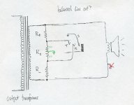
Question: could you balance the Doug's Circuit version above by doing this?
https://s3.amazonaws.com/erikcameron/files/balanced_doug_out.jpg
R+ and R- set attenuation, Rz sets the output impedance, right? It seems (to me, hah!) like this should work without adding another transformer.
Thanks, as usual.
-Erik
I can think of at least one desired use that would necessitate driving long cable runs (recovery amp for a plate reverb, which may need to be physically isolated---there's a dummy load for mic pre usage) so I'd like at least one balanced output. The two circuits above are unbalanced, and the balanced versions I've seen on the web all seemed to add an additional (line) output transformer. I can't figure out why---it seems like the OT itself should be able to balanced the output for you. (And the extra iron costs money...)
Question: could you balance the Doug's Circuit version above by doing this?
https://s3.amazonaws.com/erikcameron/files/balanced_doug_out.jpg
R+ and R- set attenuation, Rz sets the output impedance, right? It seems (to me, hah!) like this should work without adding another transformer.
Thanks, as usual.
-Erik
The receiving end of the feedback is ground referenced.With this output the ground is elswhere. the feedback current flows in one half of the output divider upsetting balance and there is only half the voltage left for the feedback.
Perhaps with a very low-ohmic divider and an adapted feedback resistor it could stil work
Mona
Perhaps with a very low-ohmic divider and an adapted feedback resistor it could stil work
Mona
No, only one tap. Though I did some more reading, and I think I misrepresented the circuit. (I was looking at the Doug's Circuit version when I sketched it.) Here's the OT schematic:
https://s3.amazonaws.com/erikcameron/files/akai-ouput-ot.png
The OT secondary is tied to ground. If I understand correctly, this is both a real good idea and also prevents using the OT to generate a balanced output signal---if you did, a transformer fault would put the B+ onto the output jack. Does that sound about right?
I'll probably either just use an output transformer, or leave this unbalanced and impedance-balance the cathode output from the last preamp tube. (That's J5 in the schematic.) Though I suppose I could impedance-balance this output too? Hrmm.
Last edited:
Use a small 10K:10K audio coupling/bridging transformer.
Bad scan BUT, see bottom left corner of sheet 1. Balanced Line Output is from the wiper and the "0" of that "Line Out Level" 25K pot.
These trannies are very cheap (AUS$9.95 for the ALTRONICS M 0710 that I used), 20Hz to 30kHz which is way more than required.
Example:
Cheers,
Ian
Bad scan BUT, see bottom left corner of sheet 1. Balanced Line Output is from the wiper and the "0" of that "Line Out Level" 25K pot.
These trannies are very cheap (AUS$9.95 for the ALTRONICS M 0710 that I used), 20Hz to 30kHz which is way more than required.
Example:
Cheers,
Ian
Attachments
Last edited:
- Status
- This old topic is closed. If you want to reopen this topic, contact a moderator using the "Report Post" button.
- Home
- Amplifiers
- Tubes / Valves
- balanced post-OT line output?