2A3 Question New Post At Bottom ****
Hey guys, so for my STEM project, I am learning the basics of designing tube amplifiers. My first project is to design a simple headphone amp, and I have chosen the 6SN7 and the 2A3. Just to get a basic design going, I set up the 6SN7 as the input with a 2A3 output and an output transformer. This is pretty basic and really doesn't qualify for my project, but I ran some simulations...
When making the transformer ratio 2.5, and using a 600R load (eg. Beyer T1) I got about 7 dB gain. That was fine for a TC amp with high impedence.
The problem was when I changed my load to anything less, and adjusted the tranny turns, I got negative gain. I have tried every possible turns ratio and many different impedences from 32-100R and I can't get the thing to give me a possitive gain.
Here is a screenshot. Anything wrong with my design? I can't seem to figure this one out.
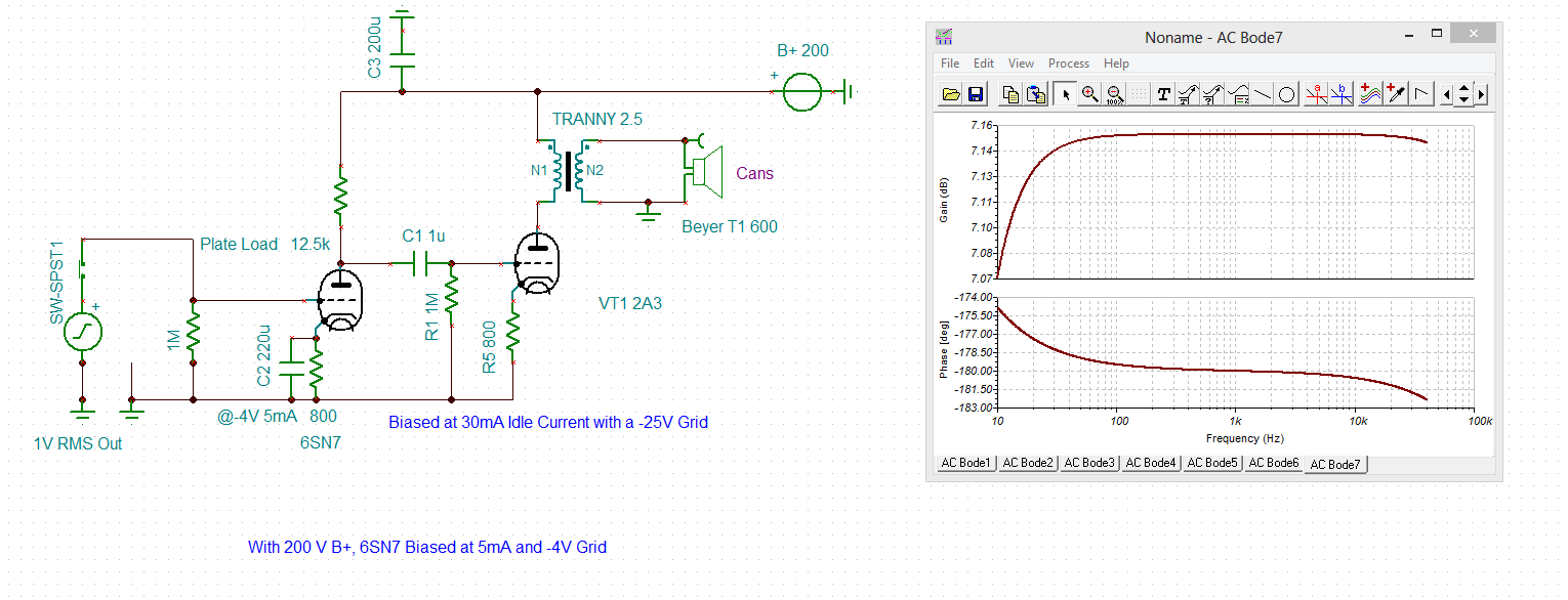
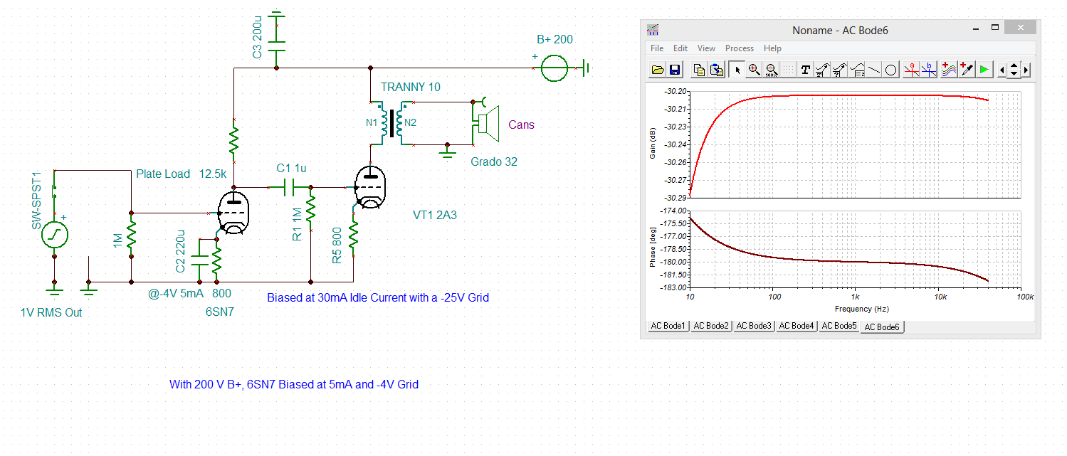
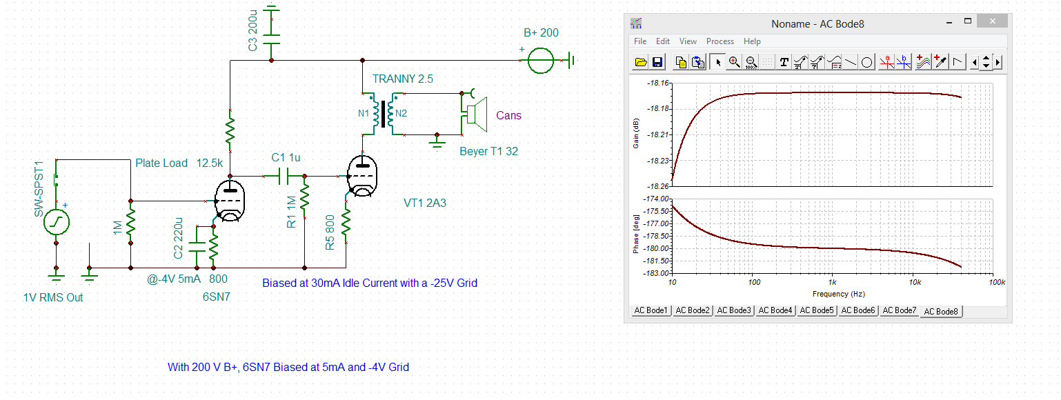
Just to reitterate, this is NOT my final design, it is simply the basis for my design, which won't be that much more complex, but still won't be quite this basic.
Hey guys, so for my STEM project, I am learning the basics of designing tube amplifiers. My first project is to design a simple headphone amp, and I have chosen the 6SN7 and the 2A3. Just to get a basic design going, I set up the 6SN7 as the input with a 2A3 output and an output transformer. This is pretty basic and really doesn't qualify for my project, but I ran some simulations...
When making the transformer ratio 2.5, and using a 600R load (eg. Beyer T1) I got about 7 dB gain. That was fine for a TC amp with high impedence.
The problem was when I changed my load to anything less, and adjusted the tranny turns, I got negative gain. I have tried every possible turns ratio and many different impedences from 32-100R and I can't get the thing to give me a possitive gain.
Here is a screenshot. Anything wrong with my design? I can't seem to figure this one out.
Just to reitterate, this is NOT my final design, it is simply the basis for my design, which won't be that much more complex, but still won't be quite this basic.
Last edited:
A step-down transformer by definition gives negative voltage gain. This may or may not make the total gain of the circuit negative. The OTs job is to make it possible for a high impedance source (such as a vacuum tube) to be able to drive low impedance devices, such as headphones and speakers.
You appear to be showing a step UP transformer in your sims...
If you change the turns ratio to maintain the same primary impedance then you will get the same POWER into the load, but this implies the VOLTAGE gain of the whole circuit will be divided by sqrt(Load 1 / Load 2). The voltage gain to the anode of the 2A2, however, should remain the same.
If you change the turns ratio to maintain the same primary impedance then you will get the same POWER into the load, but this implies the VOLTAGE gain of the whole circuit will be divided by sqrt(Load 1 / Load 2). The voltage gain to the anode of the 2A2, however, should remain the same.
Last edited:
First big problem I can see is in the driver stage, your plate load resistor is too low, needlessly reducing the available voltage gain.
I would recommend a plate resistor of minimum 3X the rp of the 6SN7..
Supply voltage should probably be boosted to the vicinity of 300V which would give you the headroom required for reasonable drive out of the 6SN7.
To drive 32 ohm headphones a step down ratio of 9:1 to 10:1 would be close to ideal with a 2A3. If you want to drive a speaker or 8 ohm headphones 18:1 - 20:1 would be about right.
Note that the cathode resistor on the 2A3 must be bypassed in order to achieve gain approaching mu, and to maintain an rp of around 600 ohms, unbypassed your rp will be much higher, substantially greater than 3K.
You should be able to achieve at least 10dB of gain from input to transformer secondary if you have done things correctly.
Related question, I can't seem to figure out how to wire the 2A3 filament. If I design a DC Supply for the filaments, how do I physically wire it. Since the filament supply would affect the Cathode voltage , how do I keep my bias at whatever voltage I have it set as with a resitor?
I understand I solder one end of the supply, the +, to the filament, and then the other part, the ground, to the other filament terminal. Where do I put my bias resistor and capacitor to ground? A diagram would help if possible, thanks!
I understand I solder one end of the supply, the +, to the filament, and then the other part, the ground, to the other filament terminal. Where do I put my bias resistor and capacitor to ground? A diagram would help if possible, thanks!
- Status
- This old topic is closed. If you want to reopen this topic, contact a moderator using the "Report Post" button.