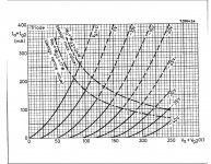
i joint the graphic to EL 504 , little distortion...
I would try to bias the PL504 well below 100 mA.
You could replace the diode at the cathode of 12AT7 with some 3k trimmer
(bypassed with 470 uF electrolytic) and with this adjust the whole amplifier to optimum linearity. (= distortion cancelling)
Ofcourse the clipping takes place at the output tube at some power level.
Edit: I made a quick simulation. A very good distortion cancelling takes place when:
- +Ub = 250 V (for 12AT7)
- R1 = 82k
- R2 = 470 k
- Rk = 560 (bypassed with big electrolytic)
- Ua = 93 V (at 12AT7)
Last edited:
Yes, for the reasons you point out artosalo. But I think JM posted to illustrate how in that case exceeding Pa+Pg2 max was feasible - I think it ends up somewhere between 'design centre max' and 'design max' in that case.I would try to bias the PL504 well below 100 mA.
AFAIK there's no pubished Ik max for 6L6 but I'm sure someone will know, I doubt it's rated for 175mA continuous. Ik max (unlike Pa max) is not something I might be tempted to exceed without expecting lifespan penalty, FWIW. Did you mention you had an EL36, that would do 175mA ?It ain´t working with the low cap values...can´t get low enough..
I have a 6L6 tube if I use it as a passtube regulator can it manage the 174mA neded for the amp??
...I have a 6L6 tube if I use it as a passtube regulator can it manage the 174mA neded for the amp??
No. That is too much for one 6L6 and maybe for two tubes too.
Triode connected 6L6/5881 goes to grid current when Ua = 100 V and Ik = 50 mA.
In other words, you must have more than 100 V to be left over the pass tube and then regulation stops when the current is 50 mA or more.
But why not a simple NFET requlator:
An externally hosted image should be here but it was not working when we last tested it.
I have tested suitable component values for three output voltage ranges.
Current limiting can be adjusted/set with R7. With 18 ohms limiting begins at some 370 mA.
Last edited:
hello All ")
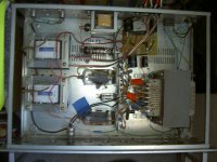
i me re build me amplificator to mode " Triode " .
i joint the curve to oscilloscope ( 23 V CaC to 1 Khz for 8 Ohms ) and the schéma for EL 504 up EL 502 .
and big stock for long live " Class A "
i me re build me amplificator to mode " Triode " .
i joint the curve to oscilloscope ( 23 V CaC to 1 Khz for 8 Ohms ) and the schéma for EL 504 up EL 502
.and big stock for long live " Class A "
Attachments
-
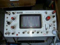 23 V Cac - 1 Khz at 8 Ohms - +_- 8 W env..JPG137.4 KB · Views: 235
 -
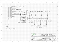 Alim HT SE EL 504 - EL 502 - 12 AT 7 - Rev 5.5 - mode Triode.jpg182.3 KB · Views: 249
 -
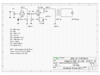 Ampli EL504 - EL 502 - 12AT7 - Mode Triode Rev 5.5.jpg176.5 KB · Views: 281
 -
 Ampli Stéréo 2 x 8 W - 2 PY 88 - 12 AT 7 - 2 EL 502 - Mode Triode.JPG404.3 KB · Views: 265
 -
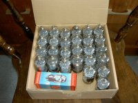 EL 502 - 28 Valve.JPG280.2 KB · Views: 193
OkIn other words, you must have more than 100 V to be left over the pass tube and then regulation stops when the current is 50 mA or more.
Now my desision is to try the SS regulator above or buy a new costomwind trafo (the one I have now is also custom made).
Im thinking..
The regulator is built and working,but I get this beeping sound from the speakers,but when I attach the DMM from - to + over the last elyt (I have C-L-C-L-C before the reg)the beeping dissapears..
Does this mean I should put a resitor from - to + on the e-lyt?
How big should the resistor be?
Does this mean I should put a resitor from - to + on the e-lyt?
How big should the resistor be?
Last edited:
- Home
- Amplifiers
- Tubes / Valves
- Question about 6P31S