Huseying,
Few things:
<snip>
I fear I fail to see the high output impedance ... A mosfet-follower into 125K? Shouldn't that be in the vicinity of 125K/mosfet gain - or what am I missing here?
<snip>
Source impedance in a follower approximates to 1/gm which should be quite low given the relatively high gm of most mosfets.
Here, try this:
Sorry, I got the schematic wrong initially; I missed the grid resistor on V2.
Could a moderator please remove the previous incorrect schematics?
Done..

Thank all of you
in the schema i put there is a resistor valued 20 M ohm , is it vital ( i get trouble to find it, also 10M ohm too) you use 680k ohm is it sufficient, or any advice about it
Thanks
The nois was hum and buzz, when i attach the preamp to the turntable the noise was magnified.What kind of noise?
Hiss? Hum? Buzz? Crackle? Microphonics?
I used 6.3v DC as heater in the previous project, and i want to use same in this project.Are you using 6V on the heaters of a 12AX7? The schematic is unclear about this.
I planned to use regulator and i will give a try to Salas' SSHV2This design has relatively poor PSRR so the supply should be really quiet. You might consider Salas' SSHV2 if it is available at the moment.
Yes my three of turntable have mm cartridge , also my friend has an another high quality Sony turntable , we test the all phono pres with it , noise was reduced but still annoying.Are you using a MM cartridge?
in couple of days i finished the first trial and again ask your advise, i planned to draw a pcb also i will post it here , i will try the 1k cathode resistor too , sorry but i coudnt understand what you mean by saying 40v dc elevation, is that on the filament ? if you can speare some time to draw a diagram it would be very helpuse a 1k cathode resistor instead. Are you wiring point-to point? Maybe the layout needs refinement, or a pcb. Metal film resistors will help minimize noise, especially in the first stage. The diagram shows the filaments in parallel by implication. You can elevate them by +40VDC or so with a resistor divider and a decoupling capacitor, taken off the B+ supply. And yes, are you using a typical output magnetic cartridge?
I will try it including mosfet and excluding mosfet. Thank you again, i will try to reply to other posts.The mosfet isn't required, the output impedance with mosfet and 125K is about same as previous stage.
Thanks I will give a try to ECC88 if i can find it, and are you also suggesting to change 2k7 kathode resistor to 1k , and do i need to change 125k to any other value ?Few things: <snip>
Advice taken , Thank you very muchThe MOSFET buffer makes a world of difference. The RCA original needs to be loaded by 250 K. The O/P impedance with the buffer is under 1 K. <snip>
The schematic I entered into LTspice was missing the grid resistor on the second tube.
Here is the corrected version:
in the schema i put there is a resistor valued 20 M ohm , is it vital ( i get trouble to find it, also 10M ohm too) you use 680k ohm is it sufficient, or any advice about it
Thanks
Although the ECC88 is somewhat quiter than the ECC83, the ECC83 is still very good -quieter than its low gm belies. Its advantage over the ECC88 is that it is nowhere near as prone to microphonics. Run an ECC83 at a reduced heater voltage (5 to 6V) and you can get the EIN down to 0.8uV!The noise generated by a tube is about inversely related to its gm, which in triodes is again related to Ia. In this respect you are certainly at a quite low gm for an input stage. In fact I would rather use a higher gm tube than ECC83 here at all. My own guess would be ECC88,
I took the original RCA circuit, modified the eq. and added a cathode follower, I'm currently using a tube regulated power supply, and regulated dc heaters, I am very impressed with its performance, and it is also very, very quiet. I only hear a faint hum if I turn volume to max!In this point i want your suggestioans , if anyone did that phono preamplifier before , please gives me some hint about it. Do i need any tweak ? , actually where i found it , some one talked about that schematic was tweaked before.
The Sovtek 12ax7WA's were very sterile sounding, and a little noisy.
Not at all surprising, as that variant has a very unsavory reputation. OTOH, the Sovtek 12AX7LPS has been consistently satisfactory.
loepke72, try this for your laplace:
laplace ((1+s*3180e-6)*(1+s*75e-6))/((1+s*318e-6)*9.897)
with Allen Wright's "50KHz pole":
laplace ((1+s*3180e-6)*(1+s*75e-6))/((1+s*318e-6)*(1+s*3.18e-6)*9.897)
Will try this later. I was trying to simulate the circuit with a .wav file input, so I was looking for 1V in = 1V out; hence the /1100 on the Laplace.
Not at all surprising, as that variant has a very unsavory reputation. OTOH, the Sovtek 12AX7LPS has been consistently satisfactory.
You are correct that is a much better tube.
The noise was hum and buzz, when i attach the preamp to the turntable the noise was magnified.
Hum and buzz would usually be from a part or assembly problem. Is it still present when shorting the inputs?
Assuming the tubes are good (check by substitution), verify that the B+ voltages are clean. Are the power supply filter capacitors fresh,
with good solder joints? Are you sure of the grounding layout? Is the circuit near a source of pickup, a transformer or a radio transmitter?
Hi,
Sounds to me as if TS has a problem with a ground loop between TT and pre though.
He says that it's there without connecting the turntable.
I have built this hybrid RIAA stage with the tweaks shown, and used Eli's idea of regulated B+ and also regulate 12V heater supply. The result is great with Sovtek 12AX7-LPS tubes, and also the new Mullard resissue long plate tubes.
I had some hum that required being sure the two regulated supplies' 0 volts were tied together at the first cap in the B+ suppy and the heater supply, along with a star connection to the 0 Volt rail of the preamp circuit. There is very little "hiss" or other noise.
I have fed this into amps using both 10K and 100K input impedances, and they are sound very good, from deep bass to the top end.
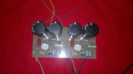
Here is the power supply I used with this phonostage:
I had some hum that required being sure the two regulated supplies' 0 volts were tied together at the first cap in the B+ suppy and the heater supply, along with a star connection to the 0 Volt rail of the preamp circuit. There is very little "hiss" or other noise.
I have fed this into amps using both 10K and 100K input impedances, and they are sound very good, from deep bass to the top end.
Here is the power supply I used with this phonostage:
Attachments
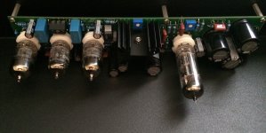
Rather beautiful!Here's a pic of the board, before installation. Currently using Tung-sol 12ax7 new issues. The Sovtek 12ax7WA's were very sterile sounding, and a little noisy.

I did a prototype , it really sillent even i didnt use any regulator.
I coudnt find a chance to perform it without mosfet but i will, nowadays im intented to do a regulator. One example was posted by Jeff Yourison , it looks pretty good but im not sure about the power performance, the datasheet of the regulater tells that the max current is no more than 30ma.
Can you tell me about its performanca Jeff, is tere any heat on the regulator.
There is something in my mind i wanna do the regulator i post here, it looks more powerfull but meanwile i tried to do the one Jeff posted. ( sorry i coudnt find the source of the psu but im sure i found it from a German site). Any one do that regulator? please give me your thougths.
Thank you
Attachments
Huseying,
Because I am using a regulator for each channel of B+, there is little excess heat at all. The current draw of the 12AX7s is very low. I have small "hat" style heat sinks in place. Same for the heater regulator, using that power transformer. With the 6.3V doubler, regulating to 12VDC doesn't use up much extra voltage. I do have a heat sink on the LM7812, but it barely feels warm. The ZVN0545A follower has no sink -- none needed.
Because I am using a regulator for each channel of B+, there is little excess heat at all. The current draw of the 12AX7s is very low. I have small "hat" style heat sinks in place. Same for the heater regulator, using that power transformer. With the 6.3V doubler, regulating to 12VDC doesn't use up much extra voltage. I do have a heat sink on the LM7812, but it barely feels warm. The ZVN0545A follower has no sink -- none needed.
For anyone who is interested, here is an LTspice schematic of the original RCA tube manual circuit (from RCA Receiving Tube Manual RC-21):
RC-30 substituted a 7025, but that is the only change.
- Status
- This old topic is closed. If you want to reopen this topic, contact a moderator using the "Report Post" button.
- Home
- Amplifiers
- Tubes / Valves
- RCA Phono Preamplifier with 12ax7