I would like to try out Rod's folded cascode (or a version of it), but he hasn't posted the biasing circuit for the BJT base. @Rod?
I use a very quiet shunt regulator in my own build. It certainly must be regulated, and noise & overall performance depends on the supply quality.
The 390, as you know, is a current source for lowest noise.
So the base must be tightly cap- coupled to the + supply. Divider (< 1K dc looking out) could be used
K369 runs 7V, to keep Igsx out of the noise picture; devices with IDSS 6-9mA seem to work the most quietly (run at IDSS).
Sorry I don't have time to transcribe it fully, I have to manage a relative's hospitalisation.
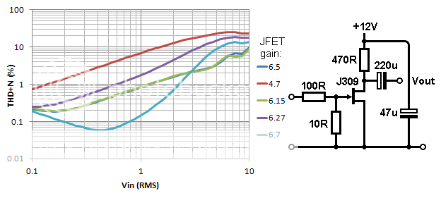
To avoid confusion with the distortion results I posted (and because I think I may have made a mistake somewhere), here is something more useful. The THD of five randomly selected J309s. I reduced the load resistor to 470R as this gave pretty much the highest gain (still not very high). Again, 1kHz, 20-30kHz masurement bandwidth.
Gate current clipping is occuring with around +0.7Vpk on the gate, which makes rather more sense! At typical MC levels (0.5mV say) it seems like even the worst FET would manage 0.05% THD.
Gate current clipping is occuring with around +0.7Vpk on the gate, which makes rather more sense! At typical MC levels (0.5mV say) it seems like even the worst FET would manage 0.05% THD.
Last edited:
Set a current source for 7mA and the gain becomes gm x Rout (2K5 here).
An externally hosted image should be here but it was not working when we last tested it.
disco,
I tried this circuit in LTSpice and get a bias current of 21.9ma for the JFET.
Might be a spice model issue, Merlins circuit produces 12%thd.
Last edited:
Hi all,
unfortunately given new job, I haven't been able to follow this very interesting thread in detail. I hope to get some time back for this.
Anyway, just wanted to share my personal experience with the folded cascode topology. I built a 72dB MC JFET RIAA stage using the K369 (+18V supply) into a BC860 darlington folded cascode and split RIAA between this first stage and a OPA627 inverting stage. The latter has a CCS to push the Op Amp into Class A.
I love the sound and I took it earlier in the year to the London Audio Circle meeting and was very well received by all. We tried Susan Parker's cartridge and sounded superb.
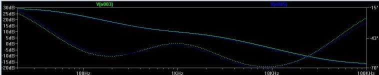
Here is the only measurement I took on the bench with no shielding whatsoever, just the breadboard - hence the noise levels. The input is my bench generator through Morgan Jones' IRIAA network:
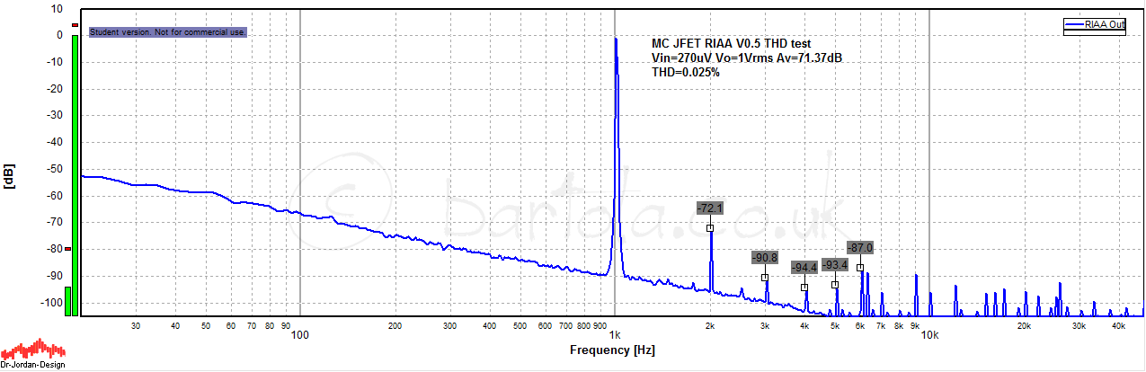
Final built version is very quiet and has an amazing sound - but this is subjective, however everyone coming to my place are asking for the RIAA!
Cheers
Ale
unfortunately given new job, I haven't been able to follow this very interesting thread in detail. I hope to get some time back for this.
Anyway, just wanted to share my personal experience with the folded cascode topology. I built a 72dB MC JFET RIAA stage using the K369 (+18V supply) into a BC860 darlington folded cascode and split RIAA between this first stage and a OPA627 inverting stage. The latter has a CCS to push the Op Amp into Class A.
I love the sound and I took it earlier in the year to the London Audio Circle meeting and was very well received by all. We tried Susan Parker's cartridge and sounded superb.
Here is the only measurement I took on the bench with no shielding whatsoever, just the breadboard - hence the noise levels. The input is my bench generator through Morgan Jones' IRIAA network:
Final built version is very quiet and has an amazing sound - but this is subjective, however everyone coming to my place are asking for the RIAA!
Cheers
Ale
Hi all,
unfortunately given new job, I haven't been able to follow this very interesting thread in detail. I hope to get some time back for this.
Anyway, just wanted to share my personal experience with the folded cascode topology. I built a 72dB MC JFET RIAA stage using the K369 (+18V supply) into a BC860 darlington folded cascode and split RIAA between this first stage and a OPA627 inverting stage. The latter has a CCS to push the Op Amp into Class A.
I love the sound and I took it earlier in the year to the London Audio Circle meeting and was very well received by all. We tried Susan Parker's cartridge and sounded superb.
Here is the only measurement I took on the bench with no shielding whatsoever, just the breadboard - hence the noise levels. The input is my bench generator through Morgan Jones' IRIAA network:
Final built version is very quiet and has an amazing sound - but this is subjective, however everyone coming to my place are asking for the RIAA!
Cheers
Ale
Nice one, Ale! I know that a K369 shunt cascode + OPA627 second-stage is an excellent solution - I tried a variant on my way to designing the phono stage shown earlier here. For the cost, and the ease of construction, it sets the highest standard of performance.
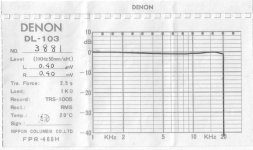
Your 270uV test (which I assume will include some noise from the generator, as well as the environment) demonstrates that you could use the stage with a Denon DL-103. The 103 gives a guaranteed level of 300uV at 1kHz 50mm/s, but this is the minimum value, and individual samples are (or were) shipped with a nice calibration plot.
Here's the actual plot for my current DL-103, showing that 400uV is available. It's not unusual for Japanese firms to be conservative with performance ratings.
Attachments
The gain of the shunt cascode stage is:
gm * Rout
where gm is the transconductance of the amplifying device (JFET in your circuit)
and Rout is the output resistor value.
gm in A/V, R in Ohm
The K369 has a gm of about 45-50 mA/V at IDSS, so your circuit will have a gain of 50.
Make Rout = 2K, and get 100.
A gain of 100 or so should suffice, whether you use an opamp for the second stage, or the triode shunt cascode.
Do you have some K369s?
Thanks Rob
Yes I have some 369s have used them before under the tube IE cathode
been building valve amps etc for 40 years mostly hobby but never got as far as transistors
But have nothing against technology the cartridge I'm using is a Ortofon sl15e output .03 m/v
would like to use a valve for the next stage (Da3)or some other pentode wired as triode but do you think it would be better to use another 2sk269 (noise)
With a gain of 100, you can use any reasonably low noise 2nd stages - valve, or opamp.
K369 is designed for very small signal input, and has high input capacitance, so is not optimal for successive stages.
Unlike MC 1st stage, a JFET 2nd stage has few advantages in fact - beyond the high dc input impedance.
You can use a triode 2nd stage, but the gain may not suffice for your system with only one stage, unless you use my shunt-cascode tuner triode suggestion; but this is an advanced build, considering the high gain and required precautions for stability.
Hi Rob
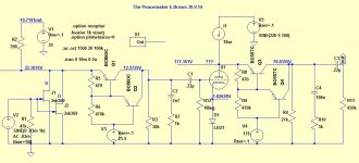
I'm getting there have called it The Peacemaker
.03m/v in 3volts out at 1k
will use buffer on output stage
valve is D3a
Comments on first stage:
- Please keep the K369 operating voltage below 15V, or else the gate will draw current, and noise performance is completely spoiled.
- 30K load resistor is too ambitious, unless a dc servo is used. 30K will need to idle at 100-200uA. The variability of the dc condition of two K369s at IDSS will exceed this! 1K - 5K, at most, is suitable without servo.
Comments on second stage:
- no need for costly D3A in second stage, unless you have traced them in constant-voltage mode and found them satisfactory. Other known-good types include EF184 (triode connected), or Russian 6Э5П (6E5P), plus other tuner types. Low cost valves can really perform in this position.
- Beware the need for ferrite beads in the main nodes, and very tight, compact construction. PCB preferred. If it's hairy, instability is assured.
- Diode 1N4148 required from V4+ (anode) to triode anode (diode cathode) to protect the base of the PNPs from reverse breakdown during turn-ON or -OFF.
- PNPs in 2nd stage should be MPSA92 or SMD KSP94 (300V+ rated)
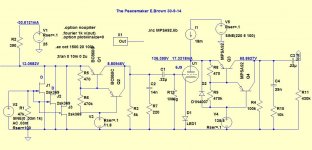
Hi Rod Have incorporated you recommendations I think?
Does this circuit behave the same as a normal circuit ie active devices when paralleled
Reduces noise as I have 3 no 369s in the circuit but can drop to 2 as I have plenty of gain (according
To spice). I have some 6j9s, have ordered some 6e5ps and mpsa92 will try on bench when they arrive
To see if theirs agreement with spice
If anyone else would like to comment please do
perhaps I should start a new thread but don’t know
how
Attachments
1st stage:
3x K369 can work, but that is a lot of current at IDSS, depending on the group you have in stock. -GR may be better (5-10mA typ).
2nd stage:
For 6J9 do you mean Russian 6Ж9П ? With this (gm = 15-20mA/V) or 6Э5П (25-35mA/V) your open loop gain (near dc) is as much as 3500! I think that 100K is too high, and may limit bandwidth, if the output drives a cable. And the dc stability is hard to achieve with 100K, too.
Seems to me to be simpler to do the whole EQ in the second stage: with 27.3K/3.9K/80n/27.7n you get near 80dB overall gain at 1kHz, using only one K369 in the first stage. These are the values I use, and dc stability is easily maintained on my amplifier, with no extra precautions.
Thanks Rob
Yes the 6j9 is the Russian 6Ж9П
No need to worry about cables will have valve buffer
Will try EQ both ways and report back on sound quality
Will now wait for the valves to arrive and test on the bench before making any more changes to the circuit
- Status
- This old topic is closed. If you want to reopen this topic, contact a moderator using the "Report Post" button.
- Home
- Amplifiers
- Tubes / Valves
- RIAA Network Position