Since their linearity is worse too, I can see no justification for using a cascode in a phono stage.
Lower input C, when that matters (MMs).
Both options (either hi-z to the filter or low-z via a buffer) have their merits.I never built one, nor do I currently intend to, so I don't have any stakes in it, but interestingly Allen Wright said quite the oppsite about his (hybrid) cascode:
"A cascode 1st stage brings several advantages:
... The high output Z means tube selection and/or aging doesn’t affect the 1st
part of the RIAA network—and with both the 3180 and 318µS points there
you don’t want too many changes …
... It is inherently quiet, linear and very fast—which is why Tek & HP used it. "
The hunt is for lowest noise and improved distortion cipher.
Last edited:
The PNP would represent a very low load impedance to the tube, so you would still get pathetic gain out of it. The result would still be more noise than if the triode were used alone with a resistive load.
All we can learn from this is that you have never built a shunt cascode stage, or considered the opportunities offered by vertical load-line operation in a number of low-cost triodes (and triode-connected pentodes).
It does not lead to low gain! Quite the opposite - it is easy to achieve a single-stage gain of 300, or even higher.
There are some obvious clues in the data-sheets of the tuner triodes, particularly the PC86 - but if you go beyond them and do your own characterisation you'll really appreciate what is possible.
to illustrate what I mean, see the attached characterisation of the PC86 (measurement of which gives the same results).
The resulting stage gives performance (low distortion, high gain, lack of EMI susceptibility, due to input & output both referred to ground) - O, and splendid sound quality.
Ultimately, a cascode involving a valve is almost never a low-noise solution, and a cascode with a tube for the bottom device is never a low-noise solution. A transistor followed by a triode can work, but it is usually better (and easier) to cascade rather than cascode them.
If you make a proper study of cascoding (well worth the effort) a few things will emerge quickly:
1. Any valve in the upstairs position will simply degrade the design.
2. A BJT will give lower noise (neighbourhood of -180dBV/rtHz per device is routinely achievable), higher gm, and hence lower distortion.
In my tests, even high capacitance brutes like the BU508 sounded better than a triode, and carefully chosen BJTs sound better still. Do your own tests to try this.
3. BJTs are better than other semis, due to the favourable relationship of capacitance, current and gm. (gm is important, as it dictates the variation in downstairs device's anode voltage.
Attachments
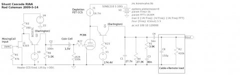
To illustrate the possibilities of a Shunt Cascode design, consider the RIAA design below.
It is designed for compatibility with Moving Coil cartridges, and in particular the Denon DL103, since no DIY design should fail to offer compatibility with this outstanding bargain - especially where your LP collection was acquired across the decades and includes samples from 1950s to 1990s pressings.
Trying to achieve MC input will either require a transformer (expensive if justice is to be done to the DL103), or you must use a JFET.
My design shows an MC RIAA that achieves 88dB (x25K) for two stages (before EQ), with low noise and ultra-low susceptibility to radiated fields.
It also has a supply current that is constant over average and instantaneous samples (allowing easy filtering) and the CCS in the valve stage allows superb rejection anyway.
See also how the active electronics do not spoil the EQ constants, because the EQ is current-fed, rather than fed by a highly imperfect voltage source, if we use a regular common-cathode stage.
Of course, shunt cascode have downsides: complexity, and need for suppression ferrites (gain is so high). But both of these are solved with a PCB, and that's what I use..... the sound is superb, using an unloved and cheap triode.
Attachments
Rod, shouldn't the coin cell be drawn on the right side of R28 for biassing the triode?
You probably found it to behave linear at sub 1V level... how about addition of noise?
hi Jaap, Yes, you are right, there's a drawing error on R28 position.
The PC86 is explicitly designed for operation at -1,5V bias at Va=175V, so there's no problems, especially for phono stage use.
Coin cell noise is low in this position, largely because the load current is in the microamp region. Maybe a bypass resistance will also be needed in some cases, if any real levels of grid current exist.
But if you can't find a low enough noise cell, or want to bias to some less convenient voltage, you can use a small-value unbypassed cathode resistor. Gm and gain degrades a little, but you have so much available already, that the phono amp will still be a success.
Some cascodes are noisier than others, so some might be worse than pentodes (though this is probably rare). All cascodes involving tubes are noisier than a cascade using the same components. Since their linearity is worse too, I can see no justification for using a cascode in a phono stage.
Producing a Cascode phono amp with worse linearity than cascaded stages simply indicates poor design work.
Comparing the linearity of Cascode vs Cascade (ie, 2-stages):
In the first place, one must use a BJT as the cascoding device (upstairs position for a series-cascode), since valves only give worse performance in every way here.
A BJT as cascoding device adds vanishing small distortion to the end result. And there's no reason why it should distort, since it is only performing the duty of current-routing.
Anyone doubting my claim here can simply prove the point by starting up LTSPICE or similar, and making a shunt-cascode with a BJT cascode device (2N5401 darlington-connected models the MPSA92 300V PNP in darlington very well). For the amplifying device, use a behavioural current source (ie, a perfect current signal).
Add a 27K load, and check out the distortion performance.
Even open-loop, the BJT adds <0.01% at respectable signal levels - and nice low order spectra declining in a well-behaved manner.
In other words, the cascoding device adds distortion which is negligible compared to the triode doing the amplification. The distortion is dominated by the amplifying device (JFET for MC stage, triode for second stage).
This too is very low, but obviously depends on the selected device and operating point.
A gain of 250-350 is easily achieved, and can be rigged to give a large output if necessary.
To equal this gain with a cascade: 2-stages are needed, which comes out about the same gain for 2 medium-mu triodes.
But with 2-stages, each producing non-negligible distortion, you must remember that the final output is a multiplication of the first-stage output by the second stage transfer function. So the spectrum produced by the first stage results in multiplication cross-products in the second - a more complicated and unnatural spectrum than the single-stage shunt-cascode gives.
Also, the susceptibility to conducted and radiated noise is degraded: you have 2 stages, each of which has input referred to ground, and output referred to V+.
Shunt cascode has IN and OUT referred to ground.
In a listening test of a real amplifier: the articulation is very notably better in the shunt cascode, among other improvements.
It gets worse, but is minimised if the EQ is driven with a cathode follower (or mu-follower).
No need for cathode follower in shunt-cascode, as the EQ-drive is a current source of much better quality than the performance of the common-cathode's voltage-source output.
You might like to read my posts before commenting. We're talking about valve cascodes (this is a valve forum). Solid-state cascodes can indeed be much quieter than valve ones, which is really just saying that transistors are quieter than valves.All we can learn from this is that you have never built a shunt cascode stage,
Yes. The lower device is the one that does the distorting, since it operates into a lower impedance load than it typically would in a cascaded design. Cascading the same transistors would still give superior noise and distortion to a cascode, since feedback would be needed to achieve the same cumulative gain. Apart from the small input capacitance noted by SY, the cascode always loses.A BJT as cascoding device adds vanishing small distortion to the end result. And there's no reason why it should distort, since it is only performing the duty of current-routing.
Last edited:
You might like to read my posts before commenting. We're talking about valve cascodes (this is a valve forum). Solid-state cascodes can indeed be much quieter than valve ones, which is really just saying that transistors are quieter than valves.
The only person limiting their discussion to valves, and only valves, is you.
Why paint yourself into a corner? Valves are suited to some circuit positions very well, other places they are third-rate. Attempting device-purity in a circuit merely results in sub-optimal performance.
The phono amplifier I showed does include triodes, in an amplifying position, and is therefore perfectly suited to discussion here.
Besides the noise question, you claimed that the cascodes showed poor linearity, and low gain, due to your misunderstandings - which I have corrected.
Yes. The lower device is the one that does the distorting, since it operates into a lower impedance load than it typically would in a cascaded design. Cascading the same transistors would still give superior noise and distortion to a cascode, since feedback would be needed to achieve the same cumulative gain. Apart from the small input capacitance noted by SY, the cascode always loses.
You still fail to understand the ability of particular triodes to operate with vertical load lines - achieving higher gain, and lower distortion than otherwise possible. Just look at the PC86 curve, and show me where the non-linearity is.
Cascading the BJTs is perfectly irrelevant, since the open-loop distortion would be so gross. The only suitable place for BJTs is the "upper" or cascode device, and not the amplifying device.
If you don't think so, then kindly offer us a worked example amplifier, as I have done -which actually proves the worth of what I am claiming, rather than just empty guessing and theorising.
OK, we can compare BJT to a triode for the upstairs device, in a series cascode:
Consider a series-cascode stage. We can use a PC86 as the amplifying (downstairs) device, since it is well-proven (and characterised) in that position.
For the upstairs device, we can compare the PC86 to the MPSA42 NPN bipolar (cost is below 5 pence/ 7 cent even in small quantity).
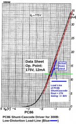
We'll run the PC86 at the data sheet operating point: 175V and 12mA.
Relevant circuit parameters:
Gm. this property determines the variation of operating voltage for the downstairs device. Higher values of gm mean smaller voltage variation, and thus lower distortion.
For PC86 at Ia = 12mA: 14mA/V. [Datasheet value]
For MPSA42: = Ic/VT = 12mA/25.3mV = approx. 470mA/V [structural value for BJT]
Output capacitance.
This will roll off the output voltage together with the load resistor, so a low value is desirable.
PC86: Cag+f: 2.1pF [Philips Data]
MPSA42: Cob for Vce of 30V+: <2pF [Motorola data]
Conclusion:
With comparable capacitance, the MPSA42 can occupy a series cascode upstairs position, and give a 30+ improvement in small-signal voltage variation for the lower device.
The BJT has smaller EMI physical profile, and no exposure to heater-borne noise.
In my highly subjective assessment, it sounded better.
The series cascode is inferior to the shunt cascode in every important way, but we cannot compare devices here, unless anyone has a P-channel thermionic FET they would like to announce.
Consider a series-cascode stage. We can use a PC86 as the amplifying (downstairs) device, since it is well-proven (and characterised) in that position.
For the upstairs device, we can compare the PC86 to the MPSA42 NPN bipolar (cost is below 5 pence/ 7 cent even in small quantity).
We'll run the PC86 at the data sheet operating point: 175V and 12mA.
Relevant circuit parameters:
Gm. this property determines the variation of operating voltage for the downstairs device. Higher values of gm mean smaller voltage variation, and thus lower distortion.
For PC86 at Ia = 12mA: 14mA/V. [Datasheet value]
For MPSA42: = Ic/VT = 12mA/25.3mV = approx. 470mA/V [structural value for BJT]
Output capacitance.
This will roll off the output voltage together with the load resistor, so a low value is desirable.
PC86: Cag+f: 2.1pF [Philips Data]
MPSA42: Cob for Vce of 30V+: <2pF [Motorola data]
Conclusion:
With comparable capacitance, the MPSA42 can occupy a series cascode upstairs position, and give a 30+ improvement in small-signal voltage variation for the lower device.
The BJT has smaller EMI physical profile, and no exposure to heater-borne noise.
In my highly subjective assessment, it sounded better.
The series cascode is inferior to the shunt cascode in every important way, but we cannot compare devices here, unless anyone has a P-channel thermionic FET they would like to announce.
No, my comments about cascodes being noisy applied to valve cascodes. For some reason you then tried to smear me by saying I knew nothing of cascodes and they were very quiet. Except you were talking about transistors.The only person limiting their discussion to valves, and only valves, is you.

Well, it appears to include one triode, although I'm not sure why. It seems to be kinda redundant. Why spoil a perfectly good solid-state discrete phono stage by shoe-horning a triode into it? Seems more like a fashion statement than an engineering advantage.The phono amplifier I showed does include triodes, in an amplifying position
You still fail to understand that for a triode, linearity is worse into a vertical load line than into a higher impedance load. This ought to be common knowledge...You still fail to understand the ability of particular triodes to operate with vertical load lines - achieving higher gain, and lower distortion than otherwise possible.
As you can see, linearity improves with load impedance. As it always does for a triode. (I'm not saying the distortion would be really bad, especially above 10mA; you have chosen an unusually good triode to bolster your claims, but it will be better still into a higher load.)Just look at the PC86 curve, and show me where the non-linearity is.
An externally hosted image should be here but it was not working when we last tested it.
Last edited:
No, my comments about cascodes being noisy applied to valve cascodes. For some reason you then tried to smear me by saying I knew nothing of cascodes and they were very quiet. Except you were talking about transistors.
I attacked your claim that PNP cascodes (which can only mean shunt cascodes) gave "pathetic gain" (your post, see post 14). That is not a smear - your made a false claim, and I corrected you by showing a high linearity stage with a gain of 300+.
The only way you can be unaware of the high-gain possibilities available with the shunt cascode is to never have analysed and/or built one - so that's what I said to you.
Well, it appears to include one triode, although I'm not sure why. It seems to be kinda redundant. Why spoil a perfectly good solid-state discrete phono stage by shoe-horning a triode into it? Seems more like a fashion statement than an engineering advantage.
You are not sure why I used a PC86? Well I suggest you try replacing the triode with a FET, a BJT, and pentode or anything else - and see how severely the linearity is degraded.
It uses a tuner-class triode in the amplifying position because the open-loop distortion is substantially lower than for any other device, (whether thermionic or solid state) - taking account of the signal amplitude.
One can see the potential linearity from the curve I posted along with the circuit.
If you think you know of a better device for that location, kindly present the circuit solution, for our review and criticism.
You still fail to understand that for a triode, linearity is worse into a vertical load line than into a higher impedance load. This ought to be common knowledge...
If you cannot get beyond simple generalisations and rule-of-thumb engineering, it is no surprise that you'll misunderstand the possibilities that operating devices with unfamiliar techniques can offer.
I already posted the Philips data that showed the splendid linearity of the PC86 in constant voltage, vertical load line mode; If we applied your generalisations, the PC86 would look like any old general purpose triode, rather than this.
As you can see, linearity improves with load impedance. As it always does for a triode. (I'm not saying the distortion would be really bad, especially above 10mA; you have chosen an unusually good triode to bolster your claims, but it will be better still into a higher load.)
Yes, of course I have chosen a device which optimises performance for the design objectives we have to address. That's what real design engineering involves.
The PC86, and a number of other purpose-designed tuner triodes are expressly designed to give highly linear Ia vs Vgk, once a threshold of Ia is passed.
Other triodes conform more closely to your limited expectation - though there are a number of valuable exceptions from among the more modern miniature high-gm triodes & triode-connected pentodes.
If I were satisfied with low to medium gain, I could have designed a horizontal load line-based stage for my phono amp.
But by using shunt cascode for a mere three stages, I can go from MC to 300B directly (Denon DL103 output to grid of a 300B).
Even if the stage linearity were only comparable to a "high impedance" loaded triode stage, I am still ahead of you by virtue of at least one stage fewer (often, two stages fewer).
We must not forget that every time you add a stage, you are performing a multiplication on the spectrum of its input (ie, adding more cross-products). Therefore, reducing the number of stages is always an advantage. Simplifying the distortion spectrum is not a minor difference.
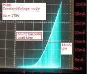
And finally, we do not need to rely on antique data sheet curves to see the linearity of a vertical load-line for the PC86. We shall need to measure, using the actual operating parameters of our design.
Forum colleague Adalin in Gotenburg traced out this curve of a real PC86 at 175V.
As you can much more easily see, an operating point of 14mA gives splendid linearity, even for +/- 6mA or more of swing! This means we can swing to the supply rails within the linear region using my 27K load, or even further if a negative supply is added.
If you believe your preferred common-cathode circuit can do better, please draw it out, characterise it, and we can review and apply the same degree of criticism.
Attachments
Last edited:
Ah, you misread my post. The gain of the cascode will be high, obviously, but I was referring to the voltage gain of the lower device (triode), which will be very low, which is bad news for SNR. For good SNR you need the first device to have as much voltage gain as possible, or at least enough to swamp the noise contribution of the second stage (upper device).I attacked your claim that PNP cascodes (which can only mean shunt cascodes) gave "pathetic gain" (your post, see post 14). That is not a smear - your made a false claim, and I corrected you by showing a high linearity stage with a gain of 300+.
Now, with a BJT for the upper device the extra noise added by the BJT may (and probably will) be negligible compared to the valve. Nevertheless, the SNR would still be better if the triode cascaded into the BJT (possibly as an emitter follower), even if it is only by 0.01dB or something. Assuming we don't care about such small figures, we might turn our attention to linearity. This will also be better if the stages are cascaded (arranged for the same gain), though the difference may also be small. In short, the cascode always gives poorer SNR and distortion than the cascaded arrangement. OK, the difference may be small -insignificant in some cases- but they are fundamentally there.
Gain stage followed by cathode/emitter/source follower would produce lower distortion and better SNR than a cascode (but also lower gain). A moot point in this case, I admit, because the noise of the second stage is irrelevent whether it is a cascode or otherwise.If you think you know of a better device for that location, kindly present the circuit solution, for our review and criticism.
Yet it will never be as linear as Va vs Vgk; the cascode always loses the linearity and noise battle; it's a fact of life. That said, if you're going to use a cascode, the folded cascode with BJT upper device is the one to go for.The PC86, and a number of other purpose-designed tuner triodes are expressly designed to give highly linear Ia vs Vgk, once a threshold of Ia is passed.
")
I don't follow this. You have four devices. Exactly the same number of devices could in principle be used in some cascaded arrangement to acheive the same overall gain.Even if the stage linearity were only comparable to a "high impedance" loaded triode stage, I am still ahead of you by virtue of at least one stage fewer (often, two stages fewer).
Last edited:
Ah, you misread my post. The gain of the cascode will be high, obviously, but I was referring to the voltage gain of the lower device (triode), which will be very low, which is bad news for SNR. For good SNR you need the first device to have as much voltage gain as possible, or at least enough to swamp the noise contribution of the second stage (upper device).
Now, with a BJT for the upper device the extra noise added by the BJT may (and probably will) be negligible compared to the valve. Nevertheless, the SNR would still be better if the triode cascaded into the BJT (possibly as an emitter follower), even if it is only by 0.01dB or something.
As you say, the difference is negligible and should not influence our decision, when the real tradeoffs are fought over linearity and distortion spectrum.
Gain stage followed by cathode/emitter/source follower would produce lower distortion
Well, I have presented the evidence for the low distortion and high gain of my circuit, and I dispute that it will be surpassed by any old "gain stage". You do not even specify the type of stage - and certainly provide no evidence for its low distortion.
....and better SNR than a cascode (but also lower gain). A moot point in this case, I admit, because the noise of the second stage is irrelevant whether it is a cascode or otherwise.
Exactly, it is irrelevant. And this is confirmed in practice by the low noise of the whole amplifier.
The advantages of high gain at low distortion, however, are not irrelevant.
I just don't see the point of plonking a triode into an ostensibly solid-state circuit. If you really want lowest distortion, an opamp would have done the job better surely?
It's not a "solid state circuit". I don't restrict myself to using one category of device for some arbitrary reason. In every position, I use the device that meets the needs of the design better than any other device. JFETs, MOSFETs, BJTs and triodes all have a place is my system design. In this case, a triode is best - and also gives the best overall sound (the purpose for which the amplifier is actually being designed).
Artificially painting yourself into a corner with device-choice restrictions merely leads to compromised designs.
Nonetheless, opamps can produce very good second stage circuits for an MC phono stage. If cost need be accounted for, I would choose the opamp. But the comparison in my case comes down to which I prefer the sound of.
Yet it will never be as linear as Va vs Vgk; the cascode always loses the linearity and noise battle; it's a fact of life. That said, if you're going to use a cascode, the folded cascode with BJT upper device is the one to go for.
I am glad that you are beginning to see the advantages of my shunt cascode circuit!
Now, I have presented evidence for the high linearity, and we seem to agree that the noise level is not an impediment in this case. The shunt cascode is certainly ahead on the linearity - gain battle, especially in terms of spectrum, which is more important in this practical amplifier solution.
I don't follow this. You have four devices. Exactly the same number of devices could in principle be used in some cascaded arrangement to acheive the same overall gain.
For a start, you are conceding that your gain-stage needs a follower - which makes two devices per stage - or three/four devices to reach the same gain as two in shunt cascode.
More importantly, you are interpreting "Stages" and "Devices" interchangeably, which is leading you astray.
A stage should have a definable input and output signal voltages (or currents), presented at input and output ports.
The shunt-cascode is more like a single-stage compound of devices.
It has only one single input signal-voltage, and one single output signal-voltage. There is only one single signal current running along the whole compound stage. I am neglecting the residual signal voltage on the anode (desirably zero) because it is so small.
This is not mere terminological pendantry.
The fact that the two devices are connected by a single dc voltage, and a operate on common signal current means that the output signal (whether you consider it a voltage or a current) includes the sum of distortion of the triode and the BJT - (with the BJT this means merely its departure from a perfect current-routing conduit). This is the essential point, that critics of my shunt cascode stage fail to grasp.... the BJT merely adds or subtracts, it does not multiply, like a gain stage.
By contrast, in a cascaded pair of ordinary gain stages, the output of the second is the multiplication of the output of the first stage - a very different situation in terms of distortion spectrum, as I have already explained.
Clearly I'm comparing apples to apples, so I mean the PC86 working into a load line that is anything but vertical.You do not even specify the type of stage - and certainly provide no evidence for its low distortion.
I don't think you actually said what was the final measured noise and distortion of the circuit. Maybe I missed it.Exactly, it is irrelevant. And this is confirmed in practice by the low noise of the whole amplifier.
The advantages of high gain at low distortion, however, are not irrelevant.
This is, admittedly, a matter of personal 'philosophy'. Mine is that a 'hybrid' circuit is one that is roughly 50% solid state, 50% valve. Yours has four transistors (including the depletion MOSFET) and one triode. At just 20% vacuum this pushes into my personal category of "solid state amp with valve for added mojo". If you truly wanted lowest distortion I presume you would use a good opamp? Certainly the valve can't compete with that...It's not a "solid state circuit".
Which is why I don't understand your use of a triode instead of an opamp...Artificially painting yourself into a corner with device-choice restrictions merely leads to compromised designs.
ooOOhh, so this isn't about measurement at all, it's about subjectivism. Well then, all bets are off. Do what you like.But the comparison in my case comes down to which I prefer the sound of.
I never claimed it wasn't a good cascode, or even that it wasn't a good circuit; it is. I only point out that a cascode -any cascode- can never be as good empirically as the cascaded alternative.I am glad that you are beginning to see the advantages of my shunt cascode circuit!
I saw the Ia/Vgs graph, but judging a curve by eye doesn't count for much. I'd rather see a THD measurment.Now, I have presented evidence for the high linearity,
Probably not an impediment, although the voltage reference use for the BJT must be exceedingly quiet.and we seem to agree that the noise level is not an impediment in this case.
I remain unconvinced.The shunt cascode is certainly ahead on the linearity - gain battle,
Subjectivism I can't argue with.especially in terms of spectrum, which is more important in this practical amplifier solution.
It doesn't need one, that's just a possible alternative. A couple of gain stages with local feedback could muster the same gain.For a start, you are conceding that your gain-stage needs a follower -
No, I'm saying two devices used in cascade give better SNR and linearity than the same two in cascode.More importantly, you are interpreting "Stages" and "Devices" interchangeably, which is leading you astray.
The shunt-cascode is more like a single-stage compound of devices.
Semantics. You can look at a cascode in those terms, and sometimes it is helpful to do so, but the fact remains that all transistors and valves are voltage controlled. The lower device may appear to have zero voltage gain, but it does, in fact, have some voltage gain (I estimate about x0.1), and that is what is amplified by the upper device. A cascode is a common-cathode stage feeding a grounded-grid stage. Yes they share the same signal current, which is to say that the upper devices represents a feedback mechanism to the lower.It has only one single input signal-voltage, and one single output signal-voltage.
It does multiply. It's just that the voltge it is amplifying is very small, so does not cover much of the BJTs transfer characteristic, and we have inherent feedback, so it is more tricky to separate the contribution of the two devices as you can with simple cascaded stages (as well as changing the spectrum).the BJT merely adds or subtracts, it does not multiply, like a gain stage.
Last edited:
I would very much like to see some noise measurements of this thing. The Denon cartridge puts out a nominal 300uV yes? And the EIN of a good JFET might be 0.3uV ish, implying you'll get no better than 60dB SNR. To me that doesn't sound good enough for MC use. What am I missing?
I would very much like to see some noise measurements of this thing. The Denon cartridge puts out a nominal 300uV yes? And the EIN of a good JFET might be 0.3uV ish, implying you'll get no better than 60dB SNR. To me that doesn't sound good enough for MC use. What am I missing?
300nV? You are off by 20dB, if not more.
The JFET is the K369, as labelled on the schematic. Part of the family of large-geometry JFETs that have been around since the 1970s.
Hard to know how you have missed these, if you are really in audio in any way. What have you designed your MC amplifier with?
The K369 shunt cascode can also be confirmed to be perfectly quiet in practice, in a real system. And even if it were not, if you have some even lower output MC, you can parallel two, three and so on, without any undue complexity. The addition of active area is simply the principle by which the low noise FETs were designed.
300nV? You are off by 20dB, if not more.
He said 300uV. That's also what Denon says.
So, do you have any comparative noise measurements?
- Status
- This old topic is closed. If you want to reopen this topic, contact a moderator using the "Report Post" button.
- Home
- Amplifiers
- Tubes / Valves
- RIAA Network Position