I found a catalog for UTC trafos, LS-6L4 are mentioned, but not the data you were seeking  Her it is:
http://www.google.se/url?sa=t&rct=j...5DczWC697hzMyJQ&bvm=bv.82001339,d.bGQ&cad=rja
Her it is:http://www.google.se/url?sa=t&rct=j...5DczWC697hzMyJQ&bvm=bv.82001339,d.bGQ&cad=rja
You all may be right about the 100 uf caps. (Is that why the bias voltage changes so slowly when I adjust the pot?) So the bias voltage will change more slowly as the B+ changes? So do I want the bias voltage to react quickly? Wouldn't that be the opposite of regulated? But then if B+ is unregulated quicker bias voltage change might be a good thing?
I was under the impression that a larger cap is needed to hold up the voltage. But then maybe that is only with a half wave?
But it doesn't seem to matter which end the pot the 470k is attached to if the wiper lifts I think? Since it is in effect a pair of resistors in parallel. If the wiper lifts it will see the 500k of the pot which will still limit the voltage to a minimum of -24 volts, not enough to damage the tube. Changing which end of the pot the 470k is connected to will only change the direction of adjustment when you turn the pot.
But then I have been wrong many times before.
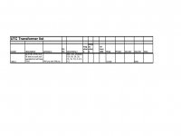
UTC LS6L4
AJT, this is what I've found on that transformer. I have a friend that might be able to get you those specs. If you decide on the primary Z you want, The secondary Z(s) He could reverse engineer them to get you the d/c resistance and the core dimensions. He could even build them for you if you like. He built me a pair of Marantz model nine power and OPT transformers and they are incredible.
AJT, this is what I've found on that transformer. I have a friend that might be able to get you those specs. If you decide on the primary Z you want, The secondary Z(s) He could reverse engineer them to get you the d/c resistance and the core dimensions. He could even build them for you if you like. He built me a pair of Marantz model nine power and OPT transformers and they are incredible.
Attachments
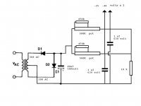
As drawn the adjustments are no longer independent of each other. Each pot needs its own 20K resistor to ground given the way you have configured the bias pots. There are a number of other problems with this design, you should drop the voltage before the pots with a series resistor and use much lower value pots. I think long ago I sent you the circuit I use?
Thanks Kevin,
Yes I've looked and looked for the circuit you sent me and can't find it in my computer. Actually, there are two 10 K resistors to ground not one. Also, the starting voltage is much higher, more like 400 volts. I had a pair of 15 k 1/2 watt pots in there and they were fried. So, to be honest, I looked around at what I had. The circuit does seem to work.
Yes I've looked and looked for the circuit you sent me and can't find it in my computer. Actually, there are two 10 K resistors to ground not one. Also, the starting voltage is much higher, more like 400 volts. I had a pair of 15 k 1/2 watt pots in there and they were fried. So, to be honest, I looked around at what I had. The circuit does seem to work.
But it doesn't seem to matter which end the pot the 470k is attached to if the wiper lifts I think?
Yes, that is in fact correct. To avoid the bias decreasing in case a wiper lifts, the pot + parallel resistor should be in the leg where the 10K resistor is now (or then the two separate 10K resistors as Kevin suggested), with a fixed resistor where the pot is now; values of resistors to suit.
I am not altogether sure why the worry about too large a smoothing capacitor with the present values. Sure, not too large - but then one also does not want half-wave ripple on the G1s. About start-up, there is more than enough time for the bias to reach effective value before power tubes start conducting.
- Status
- This old topic is closed. If you want to reopen this topic, contact a moderator using the "Report Post" button.
- Home
- Amplifiers
- Tubes / Valves
- High Voltage Derived Bias Supply