This is very basic and yet i can't seem to wrap my head around it.
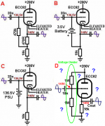
See attached pic of a valve being supplied bipolar power supply (this is actually a part of a tube active crossover). I can't understand how that valve would bias properly. As far as i see it, grid is referenced to GND via R7 (so it's at 0v) while cathode is pulled down to -100V via R4.. However, we know that valve's cathode has to be at more positive potential than grid to flow current. The way i see it, attached diagram would flow crazy amount of grid current. So how does this work?
See attached pic of a valve being supplied bipolar power supply (this is actually a part of a tube active crossover). I can't understand how that valve would bias properly. As far as i see it, grid is referenced to GND via R7 (so it's at 0v) while cathode is pulled down to -100V via R4.. However, we know that valve's cathode has to be at more positive potential than grid to flow current. The way i see it, attached diagram would flow crazy amount of grid current. So how does this work?
Attachments
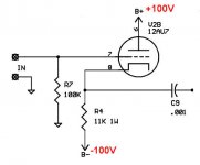
What makes you think the cathode is pulled down to 100V? It will actually be at about 0.5V (relative to circuit ground) in this configuration.As far as i see it, grid is referenced to GND via R7 (so it's at 0v) while cathode is pulled down to -100V via R4.
Here is a similar circuit. The difference is that your R4 is substituted wit a CCS.
Last edited:
What makes you think the cathode is pulled down to 100V?
I'm thinking of how an input pin of a microcontroller needs to be tied to the Vcc via some resistance to avoid the logic floating (pullup resistor). Is this not the same?
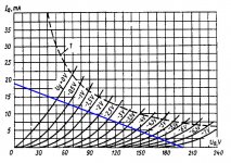
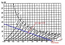
I tried drawing the load line.. This is actually 6N23P plate characteristics. So with a load of 11K and supply of bipolar +/-100V, where is the bias point?
Attachments
Member
Joined 2009
Paid Member
It's a self-regulating system. Maybe think about the tube being cold (waiting for heater), the cathode starts out near -100V as you say because there is no current flow through the cathode resistor. As the heater warms and electrons flow through the cathode resistor there will be a voltage drop. As the current increases (heater warming up) this voltage drop will increase and increase. Eventually the voltage on the cathode will reach a point where it starts to choke off the current flow through the tube. An equilibrium is reached where the current flow through the tube (without signal) is at a steady state and the voltage drop across the cathode resistor will generate a grid-cathode potential difference that maintains this current flow. You do have to choose the cathode resistor value to ensure that the steady state current flow is correct for the tube.
The 11k value you have shown looks about right and you'll see somewhere around 9mA steady state current flow.
And it's worth bearing in mind that you may have to account for some turn-on behaviour of the system when the heater first warms up.
The 11k value you have shown looks about right and you'll see somewhere around 9mA steady state current flow.
And it's worth bearing in mind that you may have to account for some turn-on behaviour of the system when the heater first warms up.
Last edited:
I tried rearranging the chart.. I think it starts to make more sense.
It no longer shows plate voltage, it shows cathode voltage instead (since plate is fixed at +100V).
Please correct me if i misunderstood something. So, at first turn on, Uk = -100V and then as the heater warms up, electrons start to escape from cathode and build up some voltage drop on the load. Slowly Uk will rise along the load line until it reaches Uk = 0V. At this voltage, Uk = Ug. Uk will no longer rise above 0V because then electrons will start to get released from grid, absorbed by cathode and finally bring it back to 0V. Hence, in the case of bipolar power supply, bias point (equilibrium) will always be the point where Uk = 0V (assuming Ug is referenced to 0v as well). Did i miss something?
Attachments
Last edited:
No, it works exactly like an ordinary cathode follower where the load resistor goes to ground, the grid leak is fed with +100V, and the anode is supplied with +200V. Except in your circuit all the voltages have been dropped by 100V. This doesn't change the way it works. The cathode will still bias up a few volts above the grid.
Last edited:
I'm sorry, i still don't get it even if you tell me to shift the voltage by 100V. There's something fundamentally wrong with my understanding, i guess.
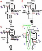
Attached pic is some configuration of CF that i took from your website. I can understand A, B and C but not D. B and C were drawn by me, while A and D were taken from your AC Cathode Follower page.
Focusing on diagram D, as with A, B and C, cathode voltage is 140V. Now there is a voltage divider of equal ratio (1M + 1M) which divides HT by 2 and the divider junction gets connected to grid. This means grid will also be at 280V/2 = 140V. So, how would diagram D bias properly with Vk being equal to Vg? If i understand diagram D, i think i would understand the bipolar case..
Attachments
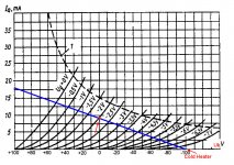
In this circuit Vk = 100 - Vak so you can re-label the horizontal axis of the plate characteristics with the values of Vk. Assuming no grid current for the time being, Vg is zero. To see where the valve biases itself, you are looking for a point on the load line where the Vk on the horizontal axis equals the -Vgk of the grid curve crossing the load line at this point. (Note the negative sign here, so for example you might have 2.5 volts on the cathode matching the -2.5 volt grid curve.)
In this circuit Vk = 100 - Vak so you can re-label the horizontal axis of the plate characteristics with the values of Vk
So, like the chart shown on post #6?
I can't see how the load line will cross the grid curve at the point where Vk = -Vgk.
>> At Vgk = -3V, Vk is still around 23V.
>> At Vgk = -2.5V, Vk is still around 12V.
>> At Vgk = -2V, Vk is 0V
>> At Vgk = -1.5V, Vk is already at around -14V
and so on.. they will not meet.
So, like the chart shown on post #6?
...
>> At Vgk = -2.5V, Vk is still around 12V.
>> At Vgk = -2V, Vk is 0V
.....
Won't they meet somewhere between the above two points?
Somewhere about Vgk = -2.17 and Vk = 2.17
Don´t overthink it.
You are trying to solve first the bias voltage and then find the cathode current which is done in 99,5% of designs, so everybody automatically assumes it´s the only way there is.
But no, the chart actually shows a relation between current, bias, and plate to cathode voltage.
You can start with ANY of those 3 variables first.
The graph will still be valid, no matter what.
Here we see that we are "imposed" one of them: an almost "fixed" current because we have a huge voltage (100V) across a large resistor (the 100K cathode one).
Please do not nitpick on percentage wise small differences, I´ll make a first approximation analysis and then adjust as (if) needed")
So: 100V across 11K=9 mA
Looking at the 12AU7 graph we find that to get 9mA through it with 100V on plate, we need slightly more than -2V so the cathode will sit slightly above +2V above ground. (above grid actually)
Basically solved !!!
In this case we can reiterate by doing it again but considering 102V across the cathode resistor and 98V plate volts, why not?
But since error is 2% or less and probably smaller than rail precision, resistor tolerance and even worse, tube characteristics spread, I guess that the first result is acceptable and any more precision will only come after actually building and measuring the particular tube you have.
Other explanations, such as considering this a single supply cathode follower are acceptable too, and yield similar results, of course
You are trying to solve first the bias voltage and then find the cathode current which is done in 99,5% of designs, so everybody automatically assumes it´s the only way there is.
But no, the chart actually shows a relation between current, bias, and plate to cathode voltage.
You can start with ANY of those 3 variables first.
The graph will still be valid, no matter what.
Here we see that we are "imposed" one of them: an almost "fixed" current because we have a huge voltage (100V) across a large resistor (the 100K cathode one).
Please do not nitpick on percentage wise small differences, I´ll make a first approximation analysis and then adjust as (if) needed
So: 100V across 11K=9 mA
Looking at the 12AU7 graph we find that to get 9mA through it with 100V on plate, we need slightly more than -2V so the cathode will sit slightly above +2V above ground. (above grid actually)
Basically solved !!!
In this case we can reiterate by doing it again but considering 102V across the cathode resistor and 98V plate volts, why not?
But since error is 2% or less and probably smaller than rail precision, resistor tolerance and even worse, tube characteristics spread, I guess that the first result is acceptable and any more precision will only come after actually building and measuring the particular tube you have.
Other explanations, such as considering this a single supply cathode follower are acceptable too, and yield similar results, of course
Sorry, I was misunderstanding your numbers, I think they should be:
Vgk = -3 Vk =-23
Vgk = -2.5 Vk =-12
Vgk = -2 Vk = 0
Vgk = -1.5 Vk = 14
But they would still meet somewhere around Vgk = -1.96 Vk = 1.96
Wow.. i'm making a lot of mistakes. Yes the mapping should be like you write! I do agree that it falls somewhere between this range:
Vgk = -2.5 Vk =-12
Vgk = -2 Vk = 0
So i agree it's around Vgk = Vk = -2.17V as you said earlier. I drew the new bias point as attached. So i'm getting around 9mA plate current as mentioned earlier.
With that said, in the case of diagram D on post #8, would Vk actually be around 143.5V, not 140V as i state in the diagram? Vg is fixed at 140V by the divider so Vgk = 140-143.5 = -3.5V.
Attachments
Don´t mess things up, please stick to original schematic and voltages, otherwise you introduce confusion while jumping from one circuit to a different one, with different voltages and resistors.
You end up showing 5 different schematics, and want to apply values found in one , to another ... does not make sense.
You end up showing 5 different schematics, and want to apply values found in one , to another ... does not make sense.
The grid is at Vg = 0, so to get the grid negative relative to the cathode the cathode needs to be positive, so I think my second version with Vgk = -1.96 and Vk = 1.96 was right.
(Actually the 1.96 is just a guess but we could get it closer if we want, by interpolation.)
Footnote: Interpolation gives Vgk = -1.93 and Vk =1.93
(Actually the 1.96 is just a guess but we could get it closer if we want, by interpolation.)
Footnote: Interpolation gives Vgk = -1.93 and Vk =1.93
Last edited:
The grid is at Vg = 0, so to get the grid negative relative to the cathode the cathode needs to be positive
yeah i agree.
i think i finally understand.. one last question just to make sure.
On the attached diagrams, only Diagram D actually has Vk more than 140V (closer to 143.5V) because Vg is fixed at 140V by the voltage divider while Diagram A, B and C have Vk at 140V. Is this statement true?
Attachments
- Status
- This old topic is closed. If you want to reopen this topic, contact a moderator using the "Report Post" button.
- Home
- Amplifiers
- Tubes / Valves
- Biasing Valve on Bipolar Power Supply