Bernard;
I've studyed the Quad II schematics, and the output stage reminds me a bit of what you are talking about. Do you know what this configuration is called? (is the quad II class A?)
What about PPP (paralell Push-pull)? I've seen a schematic over a PPP KT-88 amp, and it had an impressive distortion diagram. limited at mostly 3'rd... This was even in class AB!! Very close to a good SE amp!
Both of these configurations have something to do with what you are talking about, I think... Well, its just a thought...
Stig,
1st, have to stress that, i read a lot, i figured out many configurations, this one appealed to me. But at the moment i am talking from theory and from observations i made with other amps. No practical experiance yet with the circuit. I come back with results as soon as i have them.
The Quad II never attracted me particularly, so i do not have the schematic in mind. But, interesting to know they did soething similar, those amps have quite a rep.
The biasing is important as the tubes age. They change their plate resistance and their transconductance. I would be extremely gateful if they wold consider to that synchronously, but i am afraid, they won't do me that favour.
The CCS keeps the total constant, but the tubes get unbalanced with aging. Which is not welcomed by the output transformer at all.
LL1668: please do not waste them as CCS-replacement in the cathode, their high OPT-like core quality and inductance is neeeeeeded as plate load. As they can be wired in a centertapped, balanced mode, they are perfectly suited as plate loads in differntial pairs and, both coils being on the same core, add further help to balance the stage!
I have LL1667 and LL 1668 as plate load in preamp stage 1 and 2 and in power amp stage 1. Quite costly, and i would not consider them if i ha to buy them now.
I certainly do not waste them in the cathode.
The virtual ground of a differntial pair is quite low Z. So impedances do not have to be so big to achieve proper low frequency behaviour. I would go with PS chokes of 10-20 Hy for a 1st try (they also can handle the power).
Coloration of the CC device, be it SS or choke: i have to try this myself, i am a newbie here probably more than you")
1st, have to stress that, i read a lot, i figured out many configurations, this one appealed to me. But at the moment i am talking from theory and from observations i made with other amps. No practical experiance yet with the circuit. I come back with results as soon as i have them.
The Quad II never attracted me particularly, so i do not have the schematic in mind. But, interesting to know they did soething similar, those amps have quite a rep.
The biasing is important as the tubes age. They change their plate resistance and their transconductance. I would be extremely gateful if they wold consider to that synchronously, but i am afraid, they won't do me that favour.
The CCS keeps the total constant, but the tubes get unbalanced with aging. Which is not welcomed by the output transformer at all.
LL1668: please do not waste them as CCS-replacement in the cathode, their high OPT-like core quality and inductance is neeeeeeded as plate load. As they can be wired in a centertapped, balanced mode, they are perfectly suited as plate loads in differntial pairs and, both coils being on the same core, add further help to balance the stage!
I have LL1667 and LL 1668 as plate load in preamp stage 1 and 2 and in power amp stage 1. Quite costly, and i would not consider them if i ha to buy them now.
I certainly do not waste them in the cathode.
The virtual ground of a differntial pair is quite low Z. So impedances do not have to be so big to achieve proper low frequency behaviour. I would go with PS chokes of 10-20 Hy for a 1st try (they also can handle the power).
Coloration of the CC device, be it SS or choke: i have to try this myself, i am a newbie here probably more than you
Stig,
The Quad II (Class-A PP) and McIntosh amps (Class-AB PP) use cathode windings. This is a form of feedback. The well known ultralinear is also feedback. You may also call it Distributed Loading. In the McIntosh the load is split 50-50 between the cathode and anode. Bifilar wound transformers were used. In the Quad II, there are separate windings for the cathode and anode.
I am a stickler for transient response and dynamics. I have experimented with local and global feedback in many designs. None of them appeal to me even though they look good on scope. In other words, if you can live with a laid back presentation without the hellfire and brimstone that I like, then, by all means go for feedback.
If you are not a purist like me, then consider parallel single ended amps. I am at present developing a SE amp for Quad ESL57. There two designs; the parallel single ended topology (15W output) uses 300V on the anode and the single ended design (30W) uses 930V on the anode. Both are two stage designs and will use a specially developed output transformer that will replace the input transformer in ESL57. It will be interesting to see how these perform.
Mohan
Stigla,
The ultrapath I was thinking of was to shorten signal
path. It enables the output signal to get to the cathode
directly. I think that the beauty of the ultrapath
(earliest use of it was in WE amps!) is that it references
the output to the input directly. Remember that the
input voltage is really developed across the grid and
cathode.
If the ultrapath cap is made very large, as in
tens of uF, then I think the hum cancellation is not
effective. It is there only as a bypass to ground, no?
rgds
Yv
Mohan;
Thanks for the quad info! Hmmm, quite different to what I thought
Well, I like to think of myself as a purist, but regulary find that my wallet have other plans....
I DID (in the beginning) consider a PSE design with 2x 2A3 (andrea Cuffolini's). I designed a heck of a driver (chokeloaded 26 into a IT loaded 31!!! All DHT!!) Then, I learned som more about drivers, found that the 31 perhaps wassn't as good as I thought to drive the 2A3 (but still a good tube). And my wallet also had a few words with me
Then I read the Lynn Olson / Aurora article and thought... "Hmmm, maybe PP ain't that bad after all..." Ran over the Ralph Amp and now I am here.
One thing I do know; NO NFB!!! (gimme class A!!!!!
Yves;
So you mean like; adding a cap in the IT stage? How to calculate the value?
I know that, as I have used in the Outputstage, the cap is 3 times smaller than the BP cap. This effectively reduses ripple, as well as shorten the signal path.
But I think I will try out your advise. The Electraprint uses a 40uF... and a strange 100R resistor in the PSU end... Just to burn of Volts or has it other issuses?
Dice 45;
Have you seen the CCS thingy at Aloha Audio? Used in the Aurora amps? Interesting stuff!! (but not really a purist thing though...)
Stig
Thanks for the quad info! Hmmm, quite different to what I thought
Well, I like to think of myself as a purist, but regulary find that my wallet have other plans....
I DID (in the beginning) consider a PSE design with 2x 2A3 (andrea Cuffolini's). I designed a heck of a driver (chokeloaded 26 into a IT loaded 31!!! All DHT!!) Then, I learned som more about drivers, found that the 31 perhaps wassn't as good as I thought to drive the 2A3 (but still a good tube). And my wallet also had a few words with me
Then I read the Lynn Olson / Aurora article and thought... "Hmmm, maybe PP ain't that bad after all..." Ran over the Ralph Amp and now I am here.
One thing I do know; NO NFB!!!
(gimme class A!!!!! Yves;
So you mean like; adding a cap in the IT stage? How to calculate the value?
I know that, as I have used in the Outputstage, the cap is 3 times smaller than the BP cap. This effectively reduses ripple, as well as shorten the signal path.
But I think I will try out your advise. The Electraprint uses a 40uF... and a strange 100R resistor in the PSU end... Just to burn of Volts or has it other issuses?
Dice 45;
Have you seen the CCS thingy at Aloha Audio? Used in the Aurora amps? Interesting stuff!! (but not really a purist thing though...)
Stig
Stigla,
Yes, I mean to connect the cap from the bottom of the
IT to the cathode directly.
I hv a "cutting" of a post in the Audio Asylum that explains how
to calculate the value for the Ultrapath cap, but this is assuming
there is a bypass cap at the cathode resistor. Here it is:
"The explination for how the circuit works was described to me by thorston at the london show last year, I will try to relay my understanding of it. If the B+ rail falls, either under dynamic signal or ripple conditions, then an unwanted AC voltage will form across the OPT. To correct for this an error signal of amplitude reduced by the gain of the output stage and inverted in phase has to be fed into the grid of the output tube. A convinient way of removing the need to invert the signal is to add it into the cathode circuit so it is subtracted from the input. Since the AC conditions of the cathode are determined by the cathode by-pass capacitor, it is easy to inject this signal using a capacitive divider made with the cathode capacitor as the lower leg and an additional "ultra-path" capacitor connected between the cathode and the B+. To get the correct cancelation the AC voltage divider needs to have the correct ratio, the ultra path capacitor should therefore be the gain of the stage minus one times smaller than the cathode by-pass. Also the "ultra-path" capacitor should be of a similar construction type and characteristic to maintain this ratio over wide operating conditions.
If the value is severly wrong then positive feedback on the signal will occur, but since the dynamic impeadence characteristics of the PSU are frequency dependant, the amount of positive feed back will also be frequency dependant, causing a rise in the bass response.
HTH
Chris "
I think that in practice, one has to go about it with trial and
error to determine the best value cap, or caps in parallel if
need be. In the Electraprint circuit, I think they use the
largest value of cap that is practical since no bypass is
used at the cathode resistor. I am guessing here !
The 100 ohm looks like a filter combo when used with the
ultrapath cap.
Let us know how it works out for you.
cheers
Yv
Yves;
Thanks! So, as I understands it; If I would be using a BP cap, it would have been 220uF. Thus, the UP-cap would have been approx. 220uF / (stagegain-1) = 220 / (22-1) = 10,5uF.
But this is WITH BP cap, so it would have to be higher, yes? around 22-33uF should work... but this will be experimental stuff when I get the Amp up and running.
Do you think that the 33uF cap to a 100uF cap at the output is wrong? I read in Tube CAD, and the way I understand it it should be 3 times smaller.
Well, using your method, it goes something like; 100uf / (4,2-1) = 31,25uF. So 33uF ain't all that wrong. The value is probably not very critical, or what? The cap will have a tolerance of around 10% anyways...
Thanks for all the help everyone!!!
I cant wait to get it ready, It will be used on Klipsch RF3-MKII. 98dB /1W.
Hello Yves;
Looking about in the RCA-13 i stumbled over a so called "Class A audio frequency Amplifier" stating to provide 12 W, at page 185, using 2x 2A3 and 1x56 with an IT. Intersting circuit!
Though the Class A aspect can be discussed when the tubes are biased at 40mA and -60V....
Well, to the subject; The IT loaded 56 was the intersting bit, it had implemented Ultrapath! Though using a 5uF BP cap on a 2,2k resistor is strange, and the 2uF Ultrapath cap is well overdimensioned. Using your equations, a 5uF cap in that configuration would need only around 0,39uF...
Even more interesting is that the PSU drop resistor of 5K had NO filter cap between the IT and itself. just; 5k resistor ----> 2uF Ultrapath cap and IT primary...
Why like this? Would a filter cap from the 5k'er to ground destroy the ultrapath?
The total of the UP and the BP cap will only work as a 1,43uF cap when seen from the PSU.
This is not very unnlike the Electraprint circuit, but it had only a smallish 100R resistor. (and no BP cap.)
So, if I would try making myself a Ultrapath in the input, would I have to leave the VR tubes (0c3's) out?
Okay, finally got some parts in, and started breadboardnig. One channel.
First experiences;
hooking up all the parts where easy, then applying power to the amp, using the old light-boulb trick. Everything seemed okay, no smoke and no flashes anywhere. Good.
Removed the lightboulb and plugged in 230V to the power tranny. Waiting for some nervous 35 seconds... Hmmm, B+ of 320,6 volts... the 0c3's glowing purple... but what is this? 49,3 volts on the cathodes of the 6b4gs? errr.... hmmm, must be the higher voltage I gained from swithcing from the GZ-37 to the 6D22S's...
214 volts on the ecc99 B+. Very nice!
hmmm, 6,43 volts on the 6b4g filaments... 6,38 to the ECC99. Just a tad too high...
man, the 6D22S are getting very hot.
I let it run for a good 30 min. Then swithced the 8ohm power resistor to a speaker. Hum level to high... Guess I'll try out changing the 2 paralelled 5,1k caddock's with a 1,5k and a 1k'er in series, with a 22uF cap in the middle later today.
Well, so far I am very pleased, no smoke and just minor problems. Only thing I did'nt expect was all the heat! All the tubes get much hotter than I imagined, must take this into account when I'm to (re) design the chassis.
summary;
- a little higher filament voltage than I would like... what would be the easyest to do here?
- not the exact 45 volts I would want on the cathodes of the output-tubes. 49,3V = 98,4 mA through the tubes. Maybe Ill try out 750ohms on the cathodes giving me perhaps around 60mA and 45 volts...
- very much heat dissipated. not awefully lot, but much higher than I thought.
- A very nice light show in dim light!
- Hummm.....
I hope someone can help me out with the filament voltage-problem.... using series resistors seems like a bad idea... Probably not very exact windings on my power trannys, but I overdimensioned (for current that is...) the heaterwindings on purpose, so I guess thats the reason.
and thanks for all the help so far, would prob. not have buildt this thing if it werent for you guys!!!
Stig
Uhmm what does the circuit look like?
Stig,
Would you mind posting the RCA circuit (or yours) so we could all
comment on it? I assume you built that up, or a very
similar one.
So here goes my guess:
The 5k resistor and primary are actually
parallel loads to the 56. Ideally you want the impedance of
the resistor to be as high as possible, but that means high
B+ voltages too. If the resistor value is large enough
the impedance of the primary dominates. I think 5k is a compromise.
The 2uF cap is a parallel-feed (or parafeed) cap. It is
connected (I guess) from plate to primary, not from
primary to cathode. This configuration is different from
that of the ultrapath, where the current to plate actually
flows thru the primary itself. In this config, the cap value ca
can usually be made smaller, but it will resonate with the
primary inductance such that there will be a hump in
the low end of the freq response.
Go to www.bottlehead.com and download the latest
copy of VALVE magazine. It details how to calculate this
cap value. IMHO, this is one of the most ideal way to couple
interstages in tubes.
hope this helps.
Yv
yves,
this is not the circuit I conected up, it is just something I ran over, and started wondering. My last post is conserning the schematic I posted on at the bottom of page 1.
I've attached a small part of the schematic from RCA 13 tube manual. (not the one I used)
It is just like the Electraprint circuit, only that the 100ohm resistor is 5k and there is a bypasscap on the cathode.
what do you think?
the RCA-13 can be downloaded from
http://home.wxs.nl/~frank.philipse/frank/other.html
Attachments
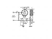
rca amp
The 5k and 2uF combo makes for a 15.9 Hz 3db point, so you
get something like 12db attenuation of 60 Hz or 18db at
120Hz of the psu ripple going into the primary.
The voltage divider formed by the 5u and 2u caps will cancel
out each other's hum if the values are done properly, seems that
your calculation shows the values are way off! I am not sure
in this case, perhaps the gurus can shed some light.
I do know that the way the 2uF cap is arrived at is to
tweak it for minimum hum and noise at the speaker, there
is one value for which that is minimum.
have fun,
Yv
thanks yves.
about my breadboarding of the amp at the bottom of page 1:
Amp is running fine now. Got rid of the hum, when I added a RC filter to the ECC99 PSU line. Have not tried out Ultrapath yet (at the input), as I have just ordered the caps. (22uF's mkp) Filament voltages stil a bit high though.... Is this life-degrading maybe?
About the bias voltage / current. Seems to have stabalized at 49,8 volts. This higher voltage is because of the higher rail voltage compared to the original I think.
the question is, how will this affect the performance? More power or more distortion, maybe both?
stig
Yves;
Just ran over a schematic for a Neumann U-47 mic preamp, using the legendary VF-14 and started wondering....
(I have redrawn from the original)
What do you think of this? Parafeed, I can see that, but the primary of the tranny goes straight to ground instead of to the cathode. Strange.
And look at the heater / cathode connection! I have never seen anything like it. Is this some sort of 'adobtation' of a IHP ( Inderictly Heated Pentode!!) to a DHP?
The heater runns on ~35 volts, but it is rated for 60 volts I think. Is this to control the emission from the cathode to enable it to be operated at lower voltages?
Hope you don't mind all this q's, but I really finds this interesting. Thanks for the tip about the Parafeed article. Great reading!
Stig
Just ran over a schematic for a Neumann U-47 mic preamp, using the legendary VF-14 and started wondering....
An externally hosted image should be here but it was not working when we last tested it.
(I have redrawn from the original)
What do you think of this? Parafeed, I can see that, but the primary of the tranny goes straight to ground instead of to the cathode. Strange.
And look at the heater / cathode connection! I have never seen anything like it. Is this some sort of 'adobtation' of a IHP ( Inderictly Heated Pentode!!)
to a DHP?The heater runns on ~35 volts, but it is rated for 60 volts I think. Is this to control the emission from the cathode to enable it to be operated at lower voltages?
Hope you don't mind all this q's, but I really finds this interesting. Thanks for the tip about the Parafeed article. Great reading!
Stig
I built it. If I remember correctly the B+ was ~315V and the current on the 2A3 ~ 60mA each. I had all the iron built by Jack at Electraprint Audio.
The amp worked VERY well. The only change I made was to share the outputs cathode R and bypass cap.
I since changed over to 300B's and tweaked a few resistor values.
I still have the amp and use it from time to time (I have about 7 amps that I rotate along with speakers).
There was a thread here going awhile back and many were questioning this, that and the other about the amp and "rebuilding" it, even a "revised" schematic was posted.
The thing is I am not sure if anyone ever built it in its original form.
I also tried a 6SN7 and a 6N1P ( both paralleled) for the front end. Gain was a bit low with the 6SN7, but the 6N1P sounded great as does the 5842.
Go for it.
AB
neuman 47
Stig,
very interesting circuit. First time I hv seen the filaments
run from B+. Like you said, probably because the filaments
require high voltage, so they save on extra windings or
transformer. The output trasformer is running in
parafeed with the 100k resistor used as a load in parallel
with the primary. The primary can be returned to cathode
or ground. If it returns to cathode, you need a higher
value cap, higher than the 0.5uF they use.
I hv not had any experience with running the 2A3 at high
voltages like yours, but it will be more linear with
higher standing current. Tube lifetime may be a problem
though. Typical filament voltages are +/- 10%, so I don't
think the higher voltages are a problem.
rgds
Yv
Thanks Yves and Andrewbee (I presume you mean the Ralp' amp, not the RCA...)
Yeah, the filaments voltage is even within 5% of rated 6,3Volts... Should not matter much.
Have had the breadborded channel running stabel and fine for some time now. Time to get that chassis finished! I'm not really bothered by tube-life so much. If they last for around 1 year, but sound really good I am satisfied.
Man, I really look foreward to listen to the thing.
Component quality is not exeptional but reasonable, Solen MKPs for UP caps, Rifa PEH200 for B+, Rifa PEG124 for cathode BP of the 6B4G, Caddocks, metal film etc... Using some PTFE silvered copper for the wiring.
I plan to upgrade whenever I can afford it. Some Black Gates here and there and so on.
Stig
Stig,
In the past I used Rifa PEH 169 (similar to your PEH 200) a lot for power supply in tube amplifiers. I used values from 220u/400V up to 1000u/400V. Later I found out that they were not sounding good at all.
They made the amlifier slow and undynamic and caused ringing in transients. I will never use them again in any equipment associated with sound reproduction. Perhaps the PEH 200 is better or perhaps other people have better experience of those than I have?
The PEH 124 is good, parallel with a good P-P cap for cathode decoupling.
Regards
- Status
- This old topic is closed. If you want to reopen this topic, contact a moderator using the "Report Post" button.
- Home
- Amplifiers
- Tubes / Valves
- Ralph Power amplifier