Hello , this is my beginner question i have this integrated amp supose to be ongaku clone with 2×845 rca tube , 2×12sn7gt , 2×ecc83 and four rectifier tubes the amp was fully restored replaced all caps with solen , mundorf , auricap , after testing everithing is ok but it seems to me that the right 845 tube is a litter brighter than left i have a picture of a module to setup bias can any one explain to me how should i setup bias where to point the probes from voltmeter i must say i dont have any specs from amp or tubes.
I know there is a high voltage and im aware of danger.
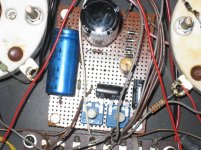
Im posting a picture of bias plate.This pictures are from prevoius not restored amp.
THX for any help
regards
I know there is a high voltage and im aware of danger.
Im posting a picture of bias plate.This pictures are from prevoius not restored amp.
THX for any help
regards
Attachments
...it seems to me that the right 845 tube is a litter brighter than left ...
What do you mean? Brighter sound or brighter light from the fillament?
The intensity of the light is not affected by the bias.
845
I mean brighter light . Im not sure but as im informed those tubes are 5-6 years old so are the rectifiers and 12sn7gt the 12ax7 ei niš was recent replacement.
thx
regards
What do you mean? Brighter sound or brighter light from the fillament?
The intensity of the light is not affected by the bias.
I mean brighter light . Im not sure but as im informed those tubes are 5-6 years old so are the rectifiers and 12sn7gt the 12ax7 ei niš was recent replacement.
thx
regards
If it's the brightness of the filaments then maybe check the filament voltages. If one is way over or way under, it may explain the difference in brightness. As mentioned above, the bias shouldn't affect this.
If it is an Ongaku clone then there are examples of the schematics on the net. I would examine those and see if it tallies to what you have wired up in the amp. Regardless, it would be a good idea to give a good look at the amp and trace a schematic for it. Should help you work out where to probe and what readings to expect roughly, especially if your planning to examine it deeper. Good luck!
If it is an Ongaku clone then there are examples of the schematics on the net. I would examine those and see if it tallies to what you have wired up in the amp. Regardless, it would be a good idea to give a good look at the amp and trace a schematic for it. Should help you work out where to probe and what readings to expect roughly, especially if your planning to examine it deeper. Good luck!
That's a nice project but I see one thing that needs attention. There are several places where wires are going through holes in the chassis. There are no rubber or plastic grommets. I know at this point it's a big job to add them, but it needs to be done. Especially with the voltages involved with tubes. You are taking a big risk because some of the through holes are pretty tightly packed with wires. They need to be enlarged and a protective grommet installed. And if the wire is Teflon™ it's all the more important because Teflon will cold form. That's what caused our space shuttle to burn up on the launch pad years ago killing all three astronauts.
845 tube amp
Can you tell me what are the purpose of those rectifier diodes and the large white is it resistor or something on the uper 845 tube socket on the picture i have strange hum-buzz only on this tube socket no mather what tube i insert in this socket.
thx
regards
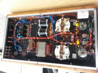
Thanks for advices and help , posting the picture after restoring i replace 12ax7 with sovtek lps there is a slight birghtness on 845 tube but the voltage is ok im leaving now amp for new parts to settle down .
regards
Can you tell me what are the purpose of those rectifier diodes and the large white is it resistor or something on the uper 845 tube socket on the picture i have strange hum-buzz only on this tube socket no mather what tube i insert in this socket.
thx
regards
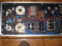
Those parts appear to be in the filament-to-cathode return network.
You have raw rectified dc supply to the filaments, using a cheap P-N bridge rectifier, and capacitors that are too small to handle the near-to 6.5A rms ripple current they will face - Especially the cap on the lower socket. These run the risk of overheating, and very short life.
This kind of arrangement will hum, and sound bad. The sound will improve hugely if you apply proper filament heating (current drive regulator).
The components there are probably an attempt to null the hum (by balancing the current into the cathode return from the dc supply). A hum pot is needed to do this correctly (100 ohm 3W pot).
But that heating scheme needs to be replaced, not fixed - the capability of the 845 will then be realised.
845 tube amp.
Are you referring from the first picture?
thx for answer
regards
Those parts appear to be in the filament-to-cathode return network.
You have raw rectified dc supply to the filaments, using a cheap P-N bridge rectifier, and capacitors that are too small to handle the near-to 6.5A rms ripple current they will face - Especially the cap on the lower socket. These run the risk of overheating, and very short life.
This kind of arrangement will hum, and sound bad. The sound will improve hugely if you apply proper filament heating (current drive regulator).
The components there are probably an attempt to null the hum (by balancing the current into the cathode return from the dc supply). A hum pot is needed to do this correctly (100 ohm 3W pot).
But that heating scheme needs to be replaced, not fixed - the capability of the 845 will then be realised.
Are you referring from the first picture?
thx for answer
regards
Are you referring from the first picture?
thx for answer
regards
The picture in Post 7.
The resistors on the filament terminals [top-right + bottom left]
are used to mix the cathode current form each filament terminal.
THe dc supply rectifier + cap is on the left of each socket. These are the parts that look under-rated.
This is not very complex circuit. I would start with drawing a schematic for it. Then measure voltages at all tubes (cathode, grid, plate).
I do not think that current regulator is a must for filament supply, enough capacitance should be sufficient. But we need to know how much is there right now before making conclusion.
I do not think that current regulator is a must for filament supply, enough capacitance should be sufficient. But we need to know how much is there right now before making conclusion.
I do not think that current regulator is a must for filament supply, enough capacitance should be sufficient. But we need to know how much is there right now before making conclusion.
Since the filament of a directly heated valve is the cathode, anything that shows up there will end up on the speaker terminals. Therefore the heater supply needs to be very clean. Even ac sounds better than simply rectified and buffered with a large electrolytic.
I use a switching supply for the 10V/5A for my 813's. Small and efficient. Chassis cooling is enough for these regs.
I have SE amp with 845. It uses bridge rectifier and large capacitor. Each tube has its own transformer winding. Works quite well without any special hum handling circuit.Since the filament of a directly heated valve is the cathode, anything that shows up there will end up on the speaker terminals. Therefore the heater supply needs to be very clean. Even ac sounds better than simply rectified and buffered with a large electrolytic.
I use a switching supply for the 10V/5A for my 813's. Small and efficient. Chassis cooling is enough for these regs.
Of cause current source will be better, but then you need special measures against high frequency noise. Amplifiers often have resonances in hundreds kHz range - right where SMPS works. This can have worse results.
845 set
Can some one tell me what are the white square electronic components between the large and small tube socket they are on both sides.
thx
regards
Thanks for advices and help , posting the picture after restoring i replace 12ax7 with sovtek lps there is a slight birghtness on 845 tube but the voltage is ok im leaving now amp for new parts to settle down .
regards
Can some one tell me what are the white square electronic components between the large and small tube socket they are on both sides.
thx
regards
Can some one tell me what are the white square electronic components between the large and small tube socket they are on both sides.
thx
regards
They are the grid coupling capacitors. (Couple the signal from driver tube to 845 power triode).
There are 2 caps in series (presumably, the driver supply voltage is higher than the cap ratings).
BTW, reasons to avoid the raw rectified filament supply:
The ends of the filament have a music signal across them, because the filament voltage causes a slope in the bias and gm of the triode.
feeding the 845 filament with raw dc exposes this small signal to the ripple of the dc supply. It also shorts the music signal through the electrolytic cap, which is also carrying the rectifier recharge (and reverse recovery) pulses.
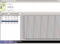
The PSUD2 screen shot shows that even with a 33000uF cap, the ripple will be near to 900mV pp, and the recharge pulses have 13A peaks.
So, it may function, but the degraded sound is no surprise.
Any DHT really gives its best when the signal at the ends of the filament is not shorted at all, and especially, the impedance looking out of the filament should not form some kind of unwanted EQ. A flat, high-impedance drive (ie current) is required for good performance.
The ends of the filament have a music signal across them, because the filament voltage causes a slope in the bias and gm of the triode.
feeding the 845 filament with raw dc exposes this small signal to the ripple of the dc supply. It also shorts the music signal through the electrolytic cap, which is also carrying the rectifier recharge (and reverse recovery) pulses.
The PSUD2 screen shot shows that even with a 33000uF cap, the ripple will be near to 900mV pp, and the recharge pulses have 13A peaks.
So, it may function, but the degraded sound is no surprise.
Any DHT really gives its best when the signal at the ends of the filament is not shorted at all, and especially, the impedance looking out of the filament should not form some kind of unwanted EQ. A flat, high-impedance drive (ie current) is required for good performance.
Attachments
845 set.
THX @Rod for helping me out with this amplifier so if im at correct understanding i need to provide 10v filament for those two 845 tubes separately with some regulators or something similar and remove all those resistors and diodes that are across the filament on 845 tubes.
thx
regards
BTW, reasons to avoid the raw rectified filament supply:
The ends of the filament have a music signal across them, because the filament voltage causes a slope in the bias and gm of the triode.
feeding the 845 filament with raw dc exposes this small signal to the ripple of the dc supply. It also shorts the music signal through the electrolytic cap, which is also carrying the rectifier recharge (and reverse recovery) pulses.
The PSUD2 screen shot shows that even with a 33000uF cap, the ripple will be near to 900mV pp, and the recharge pulses have 13A peaks.
So, it may function, but the degraded sound is no surprise.
Any DHT really gives its best when the signal at the ends of the filament is not shorted at all, and especially, the impedance looking out of the filament should not form some kind of unwanted EQ. A flat, high-impedance drive (ie current) is required for good performance.
THX @Rod for helping me out with this amplifier so if im at correct understanding i need to provide 10v filament for those two 845 tubes separately with some regulators or something similar and remove all those resistors and diodes that are across the filament on 845 tubes.
thx
regards
I believe that the extra components have been added to the filament terminals to try to control the noise and humm, which is likely, when only a raw dc supply is used.
You could improve the raw dc supply, to make it reliable, and quieter. you will need much bigger capacitors, and some series filtering.
This can lead to a quieter system, but problems will remain:
- the variation of filament voltage follows the mains tolerance, plus drops in the house. For example UK mains is allowed +/- 10%. this is enough to shorten the life of 845s. It's better to keep the voltage at 2-5% of the nominal 10V.
- the raw dc supply will allow some part of the rectifier recharge, and reverse recovery pulses.
- the electrolytic will short out the signal across the filament.
These last two problems will degrade the sound. You can find a better solution with a "CCS filament regulator" - which blocks the rectifier noise/current pulses and presents high impedance to the filament. With a CCS filament regulator, you remove the extra parts, which are only to try to fix a bad solution!
- Status
- This old topic is closed. If you want to reopen this topic, contact a moderator using the "Report Post" button.
- Home
- Amplifiers
- Tubes / Valves
- 845 set bias.