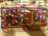
I'm an amateur trying to restore an old record player (Sonic Capri from 1955) that buzzes/hums when turned on. I've replaced nearly everything: capacitors and resistors with new ones of equal value, replaced the 25C5 tube with a good-tested tube, and I replaced the selenium rectifier with the 1N4007 as recommended on many web sites. I cleaned the POTS also. I don't have the schematics so I did the best I could with the photo here (but I'd love to get a copy if anyone has the schematics). The problem is that the system still hums just as it did before I started, and I get no response at all when the needle is touched. Oddly, or perhaps not, pin 5 has no contact with anything on the board, and I don't know if this is normal or not. Any advice appreciated. Thank you in advance.
Attachments
Your old record player does not appear to have a mains transformer. If so, this topic of discussion is not allowed.
See note #2 in the notes section.
http://www.diyaudio.com/forums/site-announcements/167561-diyaudio-rules.html
See note #2 in the notes section.
http://www.diyaudio.com/forums/site-announcements/167561-diyaudio-rules.html
Last edited:
Yo Scott,
Pin number 5 is a second connection to the control grid of a 25C5. It parallels pin 2 so no connection is normal if pin 2 is used. Regarding the hum, have you checked/replaced the electrolytic filter capacitor(s) in the PS. Also, an open cartridge can cause a hum by leaving the input unloaded and would explain the insensitivity of the stylus. Many of these were crystal and go open as a failure mode. Try momentarily shorting the input to see if the hum stops.
Pin number 5 is a second connection to the control grid of a 25C5. It parallels pin 2 so no connection is normal if pin 2 is used. Regarding the hum, have you checked/replaced the electrolytic filter capacitor(s) in the PS. Also, an open cartridge can cause a hum by leaving the input unloaded and would explain the insensitivity of the stylus. Many of these were crystal and go open as a failure mode. Try momentarily shorting the input to see if the hum stops.
Last edited:
Possible fix - missing electrolytic capacitors
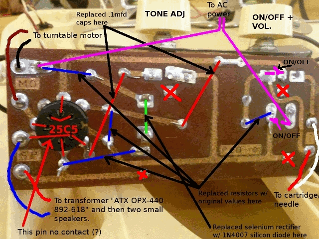
Someone contacted me and said the two bottom Xs (solder points) in the photo need to be connected by a electrolytic capacitor, and another capacitor needs to go from the right X to the bottom of the green line where the selenium rectifier connects to a resistor.
I'm going to try this and see what happens, as I discovered solder traces at those points where something used to exist... capacitors, I hope.
cap polarity and UPGRADE recommendations please
DF96 - yes, I was told the negative on both caps will go to the X on the bottom right in the photo. thank you for your concern. I am an amateur but am very safe.
hoff70 - I did not plan to alter the original layout but I'm very interested in ANYTHING that can improve this record player. Can you give me a few more details about adding an isolation transformer? brands, spec recommendations or location would help a lot. I'll also do some reading. Thank you.
ANY other improvement recommendations GREATLY appreciated.
I'm pretty newbish myself but I believe that's a "hot chassis" amp. Do some searching on it and it'll tell you more than I can! The chassis of those are connected to the mains neutral so If you plug it in backwards then the chassis is connected to the hot wire 
These are the cheapest of the cheap tube amps but I think it's interesting!
I'm fooling with an old hot chassis amp and picked up an N68-X isolation transformer which seems to be popular with these little amps. I also got rid of the selenium diode and replaced it with a full wave rectifier. The old selenium jobbie is half-wave and that's supposed to cause hum as well as making the iso trans run warm.
Less than $20 worth of parts and supposed to be both performance and safety improvements!
Hopefully someone more informed than myself will weigh in and clarify.
Update and question about crystal cartridge replacement or new circuit
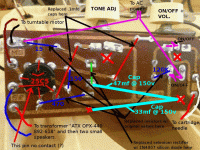
Someone recommended I install the following electrolytic capacitors and I did so as seen in the new image:
1. 47mf @ 150v
2. 33mf @ 150v
They were soldered in where indicated in the attached image (negatives to the "X" at bottom right and positives to bottom left "X" and to below the 1N4007 silicon diode (bottom of vertical green line), the location of the former selenium rectifier.
These capacitors stopped the hum/buzz and now the mono cartridge pickup "wire" gives the necessary feedback to the speakers, BUT the crystal cartridge is now dead powder, so I need to 1. buy a new old stock (NOS) crystal cartridge OR 2. add a phono preamp circuit to the board in the image. Any recommendations or directions greatly appreciated. I can hardly read schematics, so please keep it simple.
Scott
Attachments
I think I'd look for another cartridge and go from there. I believe the old ceramic carts were pretty high gain of about .5 volts. Maybe find a similar looking one on ebay and try it out?
You could use a modern magnetic cartridge with a high tracking force and a RIAA pre amp but I don't see the point with a mono amp?
Hopefully someone with more smarts will chime in but congrats on progress!
You could use a modern magnetic cartridge with a high tracking force and a RIAA pre amp but I don't see the point with a mono amp?
Hopefully someone with more smarts will chime in but congrats on progress!
- Status
- This old topic is closed. If you want to reopen this topic, contact a moderator using the "Report Post" button.
- Home
- Amplifiers
- Tubes / Valves
- 1955 kids record player hum puzzle