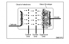
Look at this schematic, there are two weird pentode connections in "quasi triode" mode (V1-V2 and V3-V4):
http://frank.pocnet.net/other/AWV_Radiotronics/ckt/AWV_25W_Amplifier_A518_1950_a.pdf
V1 and V2 have G3 (suppressor) and Plate connected to ground and G2 (screen) used as a triode plate.
V3 and V4 have G2, G3 and Plate connected togheter, this means MU and plate resistance = low
Another weird connection:
Inverted triode (for OTL), input to plate, output to grid.
http://diyaudioprojects.com/mirror/members.aol.com/sbench102/output.gif
Last edited:
That is a not frecuently connection it is used just for more output drive in this case for lowering the Ri of the pentode (quasi triode) look carefull you can clearly see that the plate, G3 and G2 are tied together and then conected by a 100K resistor to the HT supply.
V1 and V2 are plain insane connection. G2 is used like a plate but you cant just tie G3 and plate and ground it
At least it would be just a little more negative than the cathode and G2 would atract a lot more electrons from them, but I dont know, also the plate its no treated to "give" electrons like the cathode but who knows also it may kill G2 exceding it´s power limit.

Last edited:
I know there is another unusual pentode "triode like" connection:
G3 driven
the tube is configured with the g3 (suppressor grid) as the signal input, g1 grounded (0 volts) and the g2 (screen) at a constant 90VDC.
The MU of the resulting triode like device is high.
G3 driven
the tube is configured with the g3 (suppressor grid) as the signal input, g1 grounded (0 volts) and the g2 (screen) at a constant 90VDC.
The MU of the resulting triode like device is high.
Last edited:
I understand using a pentode as a triode (using g2 as the anode) with the anode grounded can reduce noise and hum. The anode acts as a shield. Of course, you need to ensure that g2 dissipation limit is not exceeded but this should be no problem in a small signal stage.
Connecting g2, g3 to the anode is a more common triode connection.
So what is weird?
Connecting g2, g3 to the anode is a more common triode connection.
So what is weird?
Connecting g2, g3 to the anode is a more common triode connection.
Not really, usually g3 is connected to ground (internally) and g2 is connected to plate to obtain a quasi triode.
If g3 is not internally connected, then in triode mode connecting it to either anode or ground shouldn't make much difference. I always choose anode.
Pilovis,
I agree, I looks a bit weird to a noob like me.
Grounded anode is not seen every day in audio amp's. I guess that there most be
some good reason to do this. Interessting, Thank you for showing it to us.
I agree, I looks a bit weird to a noob like me.
Grounded anode is not seen every day in audio amp's. I guess that there most be
some good reason to do this. Interessting, Thank you for showing it to us.
Here they use this connection for power amplifier.
Oswalds Mill Audio - Parallax PL519 | OMA Amplifiers
Oswalds Mill Audio - Parallax PL519 | OMA Amplifiers
I have heard good things about 'screen output' PL519.
Heck I might even try to disconnect the anode cap on my 813 and run it as a 22W DHT😛 What to expect in terms of output power? 5W maybe??
Might be enough...
Now how to justify getting 5W from a valve while burning up 50W in the filament alone 😱
Heck I might even try to disconnect the anode cap on my 813 and run it as a 22W DHT😛 What to expect in terms of output power? 5W maybe??
Might be enough...
Now how to justify getting 5W from a valve while burning up 50W in the filament alone 😱
- Status
- Not open for further replies.
- Home
- Amplifiers
- Tubes / Valves
- Weird pentode connections