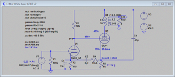
Have a look at the attached schematic.
It uses more standard resistor values and maximizes power output of the 6AH4 - now ~1.8W. Distortion is about the same.
There is one advantage in using a simple gain stage vs. the bootstrapped follower. I allows you to compensate for some treble roll off in the OPT by using a small tuning cap (Ct) at the input stage. 15nF gives about 0.7dB boost and 10° less phase shift at 20kHz. Not that you can necessarily hear this, but it makes the amp technically cleaner
Attachments
Member
Joined 2009
Paid Member
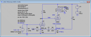
Another option would be to apply some NFB. Since the mu of the 6GK5 is quite high and the 6AH4 needs so little drive swing, the NFB can be quite substantial (for a 2-stage SET).
Look at attached schematic for a possible way how to do it. Requires only 1 additional resistor (and another 1 to change its value). Whether you like any sonic effect from NFB or not is debatable, but for difficult speakers, the damping factor rises to ~6.7 from the usual 2.5 or so.
Look at attached schematic for a possible way how to do it. Requires only 1 additional resistor (and another 1 to change its value). Whether you like any sonic effect from NFB or not is debatable, but for difficult speakers, the damping factor rises to ~6.7 from the usual 2.5 or so.
Attachments
Last edited:
Member
Joined 2009
Paid Member
Another option would be to apply some NFB.
Now you're treading on dangerous ground
Have you looked at the load line for the 6AH4? It seems to have high distortion.
You have not considered this - the 6AH4GT with a mu of 8 is biased at -18.75 VDC. The driver therefore only needs to swing a bit under 38 VDC for full power output .
From my driver's quiescent point, it looks quite good to me swinging plus and minus 18.75 VDC at full power.
And who cares about full power, when 99 percent of the time it will likely be swinging plus and minus 10 VAC... or less !!
Jeff Medwin
Last edited:
May be I read your schematic wrong, the 6AH4 is loaded with 5k to 16R, right? Anyway, if the following is acceptable, then nothing to worry about...
Hi Jeff,
Full power output will be about 1.2W @ ~6% THD (mostly H2).
Last edited:
And here's an even faster settling time
Of course, a solid state rectifier is far lower in Z than a tube rectifier.
I prefer a tube rectifier in my tube amp .
Sometimes ya gotta override a simulation, and that is where it gets mighty interesting !!
Jeff Medwin
May be I read your schematic wrong, the 6AH4 is loaded with 5k to 16R, right?
5k primary load from the OPT, yes.
I would recommend the circuit/values from post #361. Not only does it yield higher output power = more headroom. It also means less distortion for any given power level.
If so, the high mu 6GK5 triode suggested by mach1 seems like a reasonable input tube candidate, usable with a variety of finals, 6AH4GT, 2A3 etc. , ( especially IF one seeks to avoid a bootstrap / cathode follower middle stage, …..which I do.) Thanks again mach1.
Jeff Medwin
Just look at the plate curves for 6GK5. I challenge you to draw a good load line with it while keeping Rp high enough...
Believe me Jeff, I've been there and done that (REAL breadboard builds - not this simulation stuff) with this tube and others like it. There is a reason they go $1 each in bulk (with still nobody buying them).
Don't let me stop you from trying though. They're soooo cheap!
Ian
Last edited:
You have not considered this - the 6AH4GT with a mu of 8 is biased at -18.75 VDC. The driver therefore only needs to swing a bit under 38 VDC for full power output .
From my driver's quiescent point, it looks quite good to me swinging plus and minus 18.75 VDC at full power.
And who cares about full power, when 99 percent of the time it will likely be swinging plus and minus 10 VAC... or less !!
Jeff Medwin
Here I am on rare occasion agreeing fully with Jeff.

If you are going to chose something with a low amplification factor, why not at least use another DHT?
I am satisfied with the raw B+ supply design with (1) just 24 Ohms of series resistances from three chokes in the B+ filter, (2) under 0.8 VAC of ripple, and (3) 200 milliseconds - for a very smooth full-settle after a 15% current step. That is fine…..
Jeff Medwin
Hi Jeff
200 milliseconds? Serious? My prototype power supply using 6AU4 settles smoothly after a 20% current step in 100 milliseconds but I'm not happy with that!
With YOUR suggestions and advice, I will be making a change this weekend that will let it settle in only about 20 milliseconds.... I am keen to see how the change will impact the sound.
What I don't understand is why should anyone be happy with 200 milliseconds? Is this post just to provoke a wider audience?
Ian
Depends a lot on what's the objective.
For fun, why not, 200mS, that's all well and good.
But for a serious, looking for best results kind of build; no.
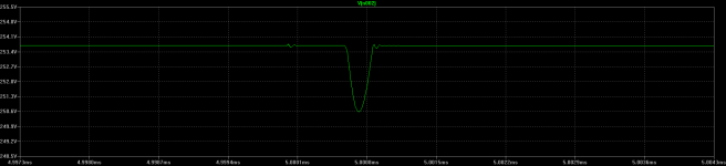
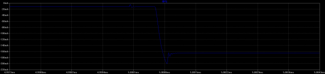
Attached plots are for a simple and crappy reg. Output impedance is around 7 to 15 ohms, depending on 'bias' (quiescent) current thru the reg.
It's more than sufficient for my fully balanced amps, that draw the exact same current all the time. For SE amps, I would look at better regs for serious results.
The PSU is absolutely critical for good sound. 200mS and several tens of ohms output impedance is simply not going to get the best results out of the SE circuit. Why cut the legs from under the nice, linear, tubes? (Except, like I said, for fun.)
For fun, why not, 200mS, that's all well and good.
But for a serious, looking for best results kind of build; no.
Attached plots are for a simple and crappy reg. Output impedance is around 7 to 15 ohms, depending on 'bias' (quiescent) current thru the reg.
It's more than sufficient for my fully balanced amps, that draw the exact same current all the time. For SE amps, I would look at better regs for serious results.
The PSU is absolutely critical for good sound. 200mS and several tens of ohms output impedance is simply not going to get the best results out of the SE circuit. Why cut the legs from under the nice, linear, tubes? (Except, like I said, for fun.)
Attachments
The PSU is absolutely critical for good sound.
I do agree with this part of what you wrote.
It's more than sufficient for my fully balanced amps, that draw the exact same current all the time. For SE amps, I would look at better regs for serious results.
I think we had this, the L-W circuit draws a (nearly) constant current from the PSU, at any time as well. Hence its reduced requirements for the PSU. It's not only about the hum cancellation..
Cheers,
GB
Member
Joined 2009
Paid Member
There remains the problem that the hum and noise of the B+ rail, injected at the cathode of the input tube is inter modulated with the input signal by the non-linear transfer curve of the input tube. It's one thing to have imperfect hum cancellation, but another to meddle with the signal. Thus providing another means for the power supply to influence the sound.
I do agree with this part of what you wrote.
Which parts do you disagree with, and why? =)
There remains the problem that the hum and noise of the B+ rail, injected at the cathode of the input tube is inter modulated with the input signal by the non-linear transfer curve of the input tube. It's one thing to have imperfect hum cancellation, but another to meddle with the signal. Thus providing another means for the power supply to influence the sound.
Did you build it yet? I did. So did Sheldon. No problems!
The sound is simply fantabulous - out of this world musical.. best darned single ended amp I ever did hear, much less build - and I live in Switzerland and often go to silly expensive high-end shows so have heard it all.... no joke, you will be shocked if you tried it.
All that though my prototype has 3VAC or ripple in the power supply that can NOT be heard. You say imperfect hum cancellation - but it works surprisingly well.
Of course I am in the process of building a better power supply for it right now. You will see in my post soon hopefully.
Ian
Last edited:
Which parts do you disagree with, and why? =)
Just the stuff about using REGS and other IC's. Every time I try it, it sounds good for a while then the sound gets tiresome. Simulates wonderfully, that is true. I know you must have heard this before. I do use REGS and other IC's in phono amplifiers, depending on the requirements.
To each their own! That is the wonderfully thing about DIY. I am sure you have perfected it and it sounds lovely for you.
btw - every time I hear the words "fully balanced" I think "snake oil". I am not alone here.
Last edited:
5k primary load from the OPT, yes.
I would recommend the circuit/values from post #361. Not only does it yield higher output power = more headroom. It also means less distortion for any given power level.
Goldenbeer,
There are things you can simulate and compute, and apply " conventional wisdom" and make you feel very confident as a designer. I can tell you right now, conventional designs won't be anything special, just another mechanical sounding audio creation .
Audio design is an ART and it requires LISTENING, not just calculating.
What you are totally unaware of is how to get the best possible sound from a Finals stage. I can see it from your proposal in Post 361. I will work through the numbers.
You lowered my Rk value from 8.7K to 6 K, increasing the current from .025A. to .02966 A. through the Finals tube. " So you get more power out ", BFD, ( I want quality at 1/10th to 3/4s of a Watt, don't CARE about over 1 Watt on my Altec speakers ). You are running 429 VDC minus 178 VDC across the Finals tube, so you are sadly dissipating 7.446 Watts of power, through a tube with a Maximum rating of 7.5 Watts. You operate it at 99.28% of the maximum rating. THAT is poor design, and you don't know it !!!
When you operate things ( say a tube, or your motor vehicle ) at 99+ percent of maximum, you are STRESSING the device. In a car, it will be subject to breaking down more. In a tube, if you are a good listener, it will sound ( to me ) as STRESSED SOUNDING as all-get -out. Why, because the tube is thermally stressed.
So, better designers, the ones who will listen to make final determinations by ear, will operate the tubes conservatively. There is a thing called the Golden Ratio, that applies to many things in this world. I suggest people keep this in mind, when setting up operating points of tubes, cars, etc.
The Golden Ratio, is about 62%, so, the car that can do 100 MPH maximum will do MUCH better when operating at 62 MPH. Likewise, a tube that has a 7.5 Watt maximum plate dissipation, will do MUCH better, and most important of all, sound better - less stressed sounding, operating at 0.62 times 7.5 Watts, or 4.65 Watts. In addition to sounding less thermally stressed, the lower dissipation will equate to perhaps 50,000 hours of usable life, rather than 10,000 hours. So, tell me, what is the better way to engineer a amp design? Better sound and longer life trumps your simulations in my opinion, any day of the week.
My Schematic has the Finals tube dissipating 5.31 Watts, or 70.8 percent of the maximum rating, and will sound better than your suggestion of running at 99 percent plus of maximum. Do NOT worry about these numbers, just LISTEN and LEARN. I have given you all a good guide, your ears will back it up !!
If you have to "hotrod" a tube to get good sound, look to improving you amp in other areas, like giving it a good supply, or properly wiring it for maximum transfer efficiency .
Jeff Medwin
Last edited:
Do NOT worry about these numbers, just LISTEN and LEARN. I have given you all a good guide, your ears will back it up !!
So you are here to give us lessons on designing tube amps, how generous of you...

- Status
- This old topic is closed. If you want to reopen this topic, contact a moderator using the "Report Post" button.
- Home
- Amplifiers
- Tubes / Valves
- 3 direct coupled 2A3 amps