Hello everyone! It's been a while since i posted but right now i'm in a little predicament and i don't really know where the fault is (if there is any).
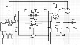
I built the preamplifier in the schematic below and it is followed by a LM3886 "typical application" circuit, the potentiometer end being connected to the preamp via a 3.3uF/ 250V capacitor.
I thought it sounds very hollow at certain bass notes, and it ruins some songs, which seems strange cause i never had this problem before with any amplifier except a full tube amp that had obviously too low damping factor for my IC-era speakers.
Now, since my last preamp that was far simpler but less worthy that drove anything from transistor amps to IC's i've been using headphones only and it's been a while. I have to also consider that i got used to the sound of headphones and that's why this thing seems strange.
I grabbed and dusted my scope and checked the amplitude after each stage doing a full frequency sweep every time. I adjusted all the controls to have precisely the same output at any frequency and same on both channels then gave it another listen. Great sounding, crystal clear, immensely detailed reproduction, but only as long as those 200-400Hz notes don't show up in any considerable amount. Those certain frequencies when they appear make everything sound way overbassy and like it's coming from an empty barrel. Now i know you're going to maybe blame the speakers but i've been using them for years now and this never happened...
I just don't know where to look. There are many possibilities and i don't know which is more likely to have the unwanted effect.
- the computer and sound card have changed since my last amp
- i never used cathode followers until now but now i was forced to by not having large value audio taper pots
- i *think* in my last LM38** i used a 47uF in it's FB circuit not 22uF as the datasheet says, maybe it could alter the way lows are produced
- could be that a cathode follower overloads (wouldn't that have shown on the scope?) which is said to have a nasty effect as opposed to a simple gain stage overloading ?
- something is not biased properly ? (but all is designed based on the tube datasheets and selecting the load line for most headroom)
PS: there's resistors imitating potentiometers in the diagram cause i do not have models for audio tapers in that software (where i also check everything before building it and checking it for real).
Attachments

Last edited:
Member
Joined 2009
Paid Member
Interesting point. You refer to the positive rail or the ground? The ground is a 1.5mm copper bar, each smoothing cap is wired to where that tube is wired as a "local star ground". I figured it would be ok but i'm open to any idea. I also went ballistic on the smoothng caps and power supply, as it is apparent in the schematic, but again anything's possible. So where do i look first?
The same ground bus (but made twice the thickness) serves the IC's which are not int the schematic. There, all that is high-current including the speaker returns go directly to the main supply caps, while the "pre ground" connections go at the last tube's ground. There's no PCB (yet) for the IC's. I think i should include them in the schematic.
The same ground bus (but made twice the thickness) serves the IC's which are not int the schematic. There, all that is high-current including the speaker returns go directly to the main supply caps, while the "pre ground" connections go at the last tube's ground. There's no PCB (yet) for the IC's. I think i should include them in the schematic.
True true...
Well, a cathode follower with a ECC88 such as that *should* in theory have less than 100 ohm impedance at it's output, at least with those values. Had it been a different valve i would no doubt have reached the same conclusion as you did.
Then perhaps i should replace that follower with say a source follower with a sturdy mosfet like IRF840 ( i got plenty of those and used them as such)?
Question: if the impedance from the cathode follower was too high, my thinking says the mids and highs would start to roll off, which does not happen says the scope ?
O-Kaay, a couple more thoughts then. Isolate the network and fit an attenuator of the same nominal impedance as the network and see if the preamp sounds "neutral". You could also squarewave test. With the controls flat, there should (ideally) be no degradation of the signal. Perhaps try that at quite high level.
You're right i should eliminate that tone control and replace it with a resistive divider to test which i'll start right away.
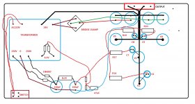
Hm.. meanwhile i'm starting to see a problem with the way the ground is routed in here, not exactly the best way. I think i'd better make it a full star ground just to be safe, or at least make separate ground paths for tube sections of V3 + 4 because... well, i have currents there opposed to each other which is really asking for trouble if putting them on the same ground wire with finite resistance. While it SEEMS to be linear in testing, it may behave badly with real music...
In lack of an actual photo, here's basically how it is:
Attachments
Ok... it seems better now. This is odd...
So, the output impedance of the cathode follower is about 77 ohms, or at least should be. So the reason it sounds awkward is... either the tube doesn't work properly or the coupling capacitor is too small for that load maybe.
Alternately i should give up the finnicky passive tone controls and adopt something wiser, like a symmetrical Baxandall active circuit. I sure got plenty of tubes here i can do whatever configuration i want. But with the lowish gain of the ECC88 the amount of correction wouldn't be that spectacular. Not that it would actually be needed. It sounds amazing with no correction, i just wanted to be fancy in designing it...
Edit: nop, won't work apparently with the Baxandhall active circuit, not with these tubes, it needs high enough gain for the tube in the Baxandhall's FB loop to be even remotely linear.
Last edited:
Got a 555 home brewed signal gen but i gotta find it first in this mess  In the meantime i will change the circuit to an active tone control. I'd post the new schematic but i'm at work now. Turns out any valve with larger gain than ECC88 can do in the tone control. Therefor i opt for ECC81 (12AT7), for i don't much like ECC83 's either noise floor or stray capacitance susceptibility.
I'll also replace the Ci in the output stage with a 47uF, that's what i used when i liked the sound of my amp. Sorry about the IC diagram in the valve section...
In the meantime i will change the circuit to an active tone control. I'd post the new schematic but i'm at work now. Turns out any valve with larger gain than ECC88 can do in the tone control. Therefor i opt for ECC81 (12AT7), for i don't much like ECC83 's either noise floor or stray capacitance susceptibility. I'll also replace the Ci in the output stage with a 47uF, that's what i used when i liked the sound of my amp. Sorry about the IC diagram in the valve section...
An externally hosted image should be here but it was not working when we last tested it.
1k and 22uf gives around 7.5Hz as a -3db point so 47uf will bring that down to around 3Hz.
The power amp as it stands is just a basic application note. It might be worth looking at the stability of it because it doesn't include a zobel network/inductor at the output stage.
Good luck with the tone control
The power amp as it stands is just a basic application note. It might be worth looking at the stability of it because it doesn't include a zobel network/inductor at the output stage.
Good luck with the tone control
Thank you!
I never had trouble with it before except when i exceeded the allowed input resistance (using a way too large value pot), then there would be very short intermittent pops sometimes when i presume the IC tried to run amok sending the output to +V or to -V then momentarily the protection cut it off.
I always use Zobel networks for chips like this. I used the one in the datasheet with 2.7R and 100nF and it's resistor never dissipated which meant there was never any ultrasonic oscillation. Maybe it's because my IC's are not genuine and have lower gain bandwidth than originals, or maybe i just got lucky.
I think i'll give the RL group at the output a try.
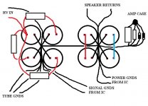
Attached here is how my old amp was wired and was also the only way the amp was dead silent, i mean really not a peep. I intend to do this one the same way
I never had trouble with it before except when i exceeded the allowed input resistance (using a way too large value pot), then there would be very short intermittent pops sometimes when i presume the IC tried to run amok sending the output to +V or to -V then momentarily the protection cut it off.
I always use Zobel networks for chips like this. I used the one in the datasheet with 2.7R and 100nF and it's resistor never dissipated which meant there was never any ultrasonic oscillation. Maybe it's because my IC's are not genuine and have lower gain bandwidth than originals, or maybe i just got lucky.
I think i'll give the RL group at the output a try.
Attached here is how my old amp was wired and was also the only way the amp was dead silent, i mean really not a peep. I intend to do this one the same way
Attachments
I used the one in the datasheet with 2.7R and 100nF and it's resistor never dissipated which meant there was never any ultrasonic oscillation.
Ahhh... now it doesn't quite work like that. The adding of the zobel stops oscillation (if its that kind of oscillation) so it wouldn't dissipate anything. Its done its job by stopping the problem. Subtle difference... do you see
Ahhh... now it doesn't quite work like that. The adding of the zobel stops oscillation (if its that kind of oscillation) so it wouldn't dissipate anything. Its done its job by stopping the problem. Subtle difference... do you see
That's what i always thought, until i saw in other threads on this forum people complaining about the resistors being fried. Or it could be their capacitors were too low voltage and were getting shorted.
May not be a cure all but in those few seconds it probably saves your tweeters from melting. By another cause... intriguing. Yes i can imagine that having no frequency limitation on the IC can cause that if a signal of sufficient frequency enters it.
On another note, the final schematic below. It's final because if this doesn't cut it i'll just leave things as they are, i don't know what else to do.
On another note, the final schematic below. It's final because if this doesn't cut it i'll just leave things as they are, i don't know what else to do.
Attachments
- Status
- This old topic is closed. If you want to reopen this topic, contact a moderator using the "Report Post" button.
- Home
- Amplifiers
- Tubes / Valves
- Tube preamplifier with chip power amp