Hi,
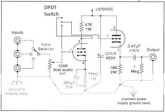
Is this OK, or would I need to add something to the VA stage output to keep it stable when not in use? A 1M to ground or something?
Is like to have a switch which allows to select between a zero gain CF/buffer and a preamp with gain.
Thank you!
Blair
Is this OK, or would I need to add something to the VA stage output to keep it stable when not in use? A 1M to ground or something?
Is like to have a switch which allows to select between a zero gain CF/buffer and a preamp with gain.
Thank you!
Blair

I just looked at my switch. It's all wrong. Not enough coffee yet. The question is still the same though. Can I break the circuit in half there with a switch without consequence, or do I need to add something to the VA stage while it is "hanging" in the off position?
Thank you!
Thank you!
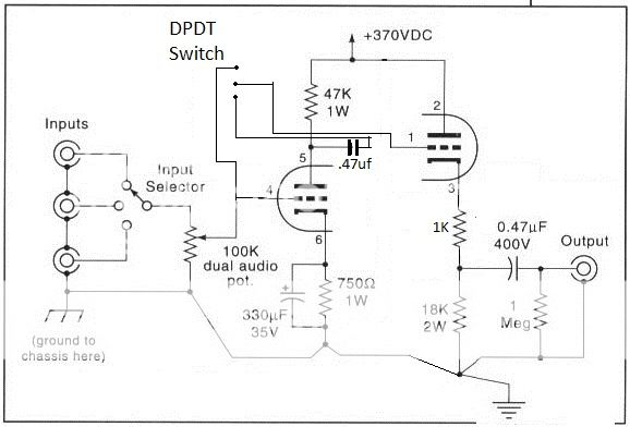
You should bias the cathode follower separately and have a cacacitor between the stages.
Now the cathode follower has bias from amplifying stage, but when switched to by-pass, there is no bias.
Now the cathode follower has bias from amplifying stage, but when switched to by-pass, there is no bias.
That will take out your speakers and ears with the bang from 0v to 100v on the second stage when switching. I agree with artosalo, separate bias and coupling capacitors are required.
Thanks guys,
Sounds a little too destructive to do in the case that someone may flip the switch when the unit is powered up.
I was altering the schematic, but this seems like a pretty bad idea.
Blair
Sounds a little too destructive to do in the case that someone may flip the switch when the unit is powered up.
I was altering the schematic, but this seems like a pretty bad idea.

Blair
Still wrong. The CF gets no bias in either switch position, and you still have the speaker/ear destroying bang on switching.
Now, even though I'm not building it, I am curious as to what the difference is between the second stage and this:
Small Improvements to White Cathode Follower Formula and Improving Cathode Followers
What would be required to achieve bias on the second stage?
Thanks,
Blair
Small Improvements to White Cathode Follower Formula and Improving Cathode Followers
What would be required to achieve bias on the second stage?
Thanks,
Blair
I don't know why Broskie claims that adding an extra resistor to the cathode follower improves linearity. It doesn't. It does isolate the CF from capacitive loads, which is why people may add it.
A quite separate issue is using a resistor in the same position to provide bias, as you appear to be trying to do. For this you need a grid resistor too, to the junction of the two cathode resistors.
To get rid of the bang, you need to ensure that all AC voltages being switched sit at identical DC voltages. This often requires extra coupling caps and high value resistors to equalise the voltages. In your circuit you would need to be careful about adding too much stray capacitance between grid and anode of the voltage amplifier, which then gets multiplied by the Miller effect.
- Status
- Not open for further replies.
- Home
- Amplifiers
- Tubes / Valves
- VA/CF 6SN7 preamp input points?