Hello Everyone,
Please look at this schematic, mainly at the FB loop electrolytic cap.
It is specified as a "copper leaf styrol" cap but I was not able to find a cap of this nature at these high values on the web, usually they are very small values and not directional.
Is this a mistake?
What is the reason for this cap?
Thank you,
Glass painter
Attachments
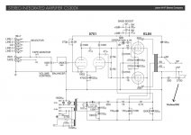
I assume you mean that 100 µF electrolytic ?
It is just for DC-blocking purpose. Usually this capacitor is not required, but now it is there due to swithcable bass boost circuit.
It can not be an ordinary electrolytic, because there is very small DC voltage (~2 V) accross it but essentially higher AC, so the polarity varies during output voltage cycle.
You are right, a bipolar is a lot better in that position. I really thought that mr. Leben would know better.
But my question is about feedback tone controls. When using bass boost in this example, we have less feedvack in low frequencies. it does not seem like a good idea to me.
But my question is about feedback tone controls. When using bass boost in this example, we have less feedvack in low frequencies. it does not seem like a good idea to me.
...When using bass boost in this example, we have less feedvack in low frequencies. it does not seem like a good idea to me.
This happens allways at low and high frequencies, even when GNFB loop has flat response. This phenomenon is emphasized with pentode connected output stages because of their high output impedance.
For example with classic Mullard 5-10 the open loop gain at 20 Hz and at 20 kHz is declined about 10 dB.
The GNFB at 1 kHz is 26 dB but at 20 Hz/ 20 kHz it is only some 16 dB.
Mullard 5-10. Ten Watt Amplifier
An externally hosted image should be here but it was not working when we last tested it.
I know this. What I am saying is that it does not look a good idea to have even less. Distortion and output impefance will rise .
What type of cap will you choose for this kind of application?
I would try to connect two ordinary 220 µF electrolytics in series but at reversed polarity and with 2 x 47 k resistors in parallel with each cacacitor.
No, the polarity stays fine - except at subsonic frequencies where the cap reactance has increased markedly. An electrolytic is OK.artosalo said:It can not be an ordinary electrolytic, because there is very small DC voltage (~2 V) accross it but essentially higher AC, so the polarity varies during output voltage cycle.
Think about it. Quiescent it has 0V at the o/p end and 2V at the input end. At a signal peak it may have 8V and 10V respectively - still biased by 2V.
I am always amazed by this misunderstanding. The 100uf cap in the feedback circuit ONLY has the cathode bias voltage of the first stage across it's terminals. The reason it is in the circuit is to block that DC voltage from grounded via the output transformer. If you were to measure the AC voltage on the cap terminals the same AC voltage would be on both terminals referenced to ground. If you measure the AC across the cap terminals it will be 0 VAC so signal voltage has no impact on the required voltage rating of the cap. A 6.3 VDC would work fine here, unless the input tube shorts. Then higher voltage could be present at the cap.
Think about it. Quiescent it has 0V at the o/p end and 2V at the input end. At a signal peak it may have 8V and 10V respectively - still biased by 2V.
Correct, I agree.
I still think as I wrote before:
"It can not be an ordinary electrolytic, because there is very small DC voltage (~2 V) accross it but essentially higher AC, so the polarity varies during output voltage cycle."
The AC-voltage at the capacitor is some 30 Vpp at full power.
The difference is that the 30 VAC is on both terminals of the cap referenced to ground, but not across the cap so the voltage rating does not need to include the 30 VAC just the DC bias voltage. Because of this it can be a low voltage electrolytic on the order of 4 to 6.3 VDC.
- Status
- This old topic is closed. If you want to reopen this topic, contact a moderator using the "Report Post" button.
- Home
- Amplifiers
- Tubes / Valves
- Leben CS300x feedback loop cap