Greetings
I am building a pair of Mono Block amplifiers based on a two channel design I am currently using. The design uses two 6.3 VAC sources to power two banks of tubes. On both tube banks the heater lead is grounded (see attached schematic) and I have not seen this grounding in other designs. My questions are:
1.) Is the grounding necessary?
2.) What is accomplished by grounding the circuit?
Thanks
Attachments
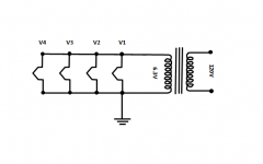
Valve heaters should always have a DC reference voltage. In many cases this is ground. The traditional way in non-critical circuits was simply to ground one side of the heater circuit - often using the chassis for the return currents. Better (for audio, but not radio) is to ground the heater winding centre tap. If there is no CT then a pair of resistors (see post 2) are almost as good. A variable resistor (known as a humdinger) can sometimes reduce hum.
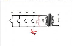
Tnx DF96 for explanation but I am not clear how to add a reference in designs where front end tube and output tube power supply is connected in series. Front end tube heater have reference to ground but output tube heaters not connected. Is it ok?
see attached picture:
see attached picture:
Attachments
AC grounding the heaters with a cap may reduce noise, especially if rectifier or mains hash is coupled through the power transformer. However on its own it does not establish the required DC potential so that needs to be done too. It is surprising how many people do not realise this, or even deny it when it is pointed out to them. Of course a direct ground connection is even better than a cap for AC grounding!disco said:What would be the reason some use 470nF - 1uF for grounding the heaters via a center tap? I always wondered why bothering with this while DC-grounding would probably have the same effect...
I once had a problem with low level spikes getting into the first stage of an amp. It had an elevated DC reference for the heater, and caps to ground for AC. However big I made the caps the spike (from the rectifiers) was still there. I scrapped the DC elevation and just grounded the heater winding CT. Spikes gone! I learnt from that to always try the simplest solution first - which often coincides with standard practice in valve circuits of 60 years ago. We usually kid ourselves when we believe that we know more than them.
Hum is also caused because the filament and cathode are conductors, separated by a small insulator (vacuum) and a semiconductor (aluminium oxide coating on the filament), and this is exactly how you make a solid-state diode. Electrons can pass from heater to cathode when the heater voltage is negative with respect to cathode voltage. When the heater voltage is below the cathode voltage, the diode is forward biased and a stray current will flow from heater to cathode causing an ugly 50Hz hum voltage to appear on the cathode, which will be mixed with our signal and amplified. If we keep the heater voltage above the cathode voltage at all times, the diode is reversed biased ('off') and almost no leakage current will flow meaning reduced hum.
Greetings
The design uses two 6.3 VAC sources to power two banks of tubes. On both tube banks the heater lead is grounded
Thanks
I think by connecting the secondary side of the transformer directly to ground is a gross mistake as it would defeat the purpose of having an isolated transformer for safety reason. I would like to hear other people opinion regarding this.
Last edited:
Ground or earth is not a safety concern, it's a safety feature. The transformer still isolates you from live and neutral, which are the dangerous wires.I think by connecting the secondary side of the transformer directly to ground is a gross mistake as it would defeat the purpose of having an isolated transformer for safety reason. I would like to hear other people opinion regarding this.
Ground or earth is not a safety concern, it's a safety feature. The transformer still isolates you from live and neutral, which are the dangerous wires.
But you also want to isolate yourself from earth/ground. By connecting the secondary side to earth, you effectively provided a conduction path to earth and this could be via a person body.
FYI: The neutral line is connect to earth at a common point. Thus they have almost the same potential, and thus they are pretty much interconnected.
Last edited:
But you also want to isolate yourself from earth/ground.
Really? That seems like a remarkable assertion.
The 6C33's (osscar) has there cathodes more than 400V above ground,don't ground the heaters.Connect them to there cathodes or let it float.The voltage drop on the anode resistor (pre) gives the negative bias for the powertubes.
Why grounding the heater supply?
First there is a cathode-heater capacity that risks to make (unwanted) interstage coupling ,so short it to ground.
Then you have also the grid nearby (and eventualy a not grounded cathode) ,it capture hum from both heater connections.By grounding a centertap the two connections are in opposite phase,balaces out.Can be adjusted with a trimmerpot.
And don't forget there is a max.Vhk .To not exeed it, it's best to have a nown potential on the heaters.
And yes some put only (TriodeDick) a capacitor between heater and ground,leaving the leakcurrent establish a voltage near the cathode that leaks the most.He claims it works fine that way.
Mona
Really? That seems like a remarkable assertion.
Well, from my understanding the whole point of having an isolated transformer is to create a floating power supply that is not referencing to earth. Any current flow should return to the other terminal on the secondary side of the transformer.
Thus let say if a person happen to touch a live copper of the heater circuit. he/she would not be electrocuted because there is no physical path for the current to return to the secondary winding terminal.
That's like a bird on a highvoltage lineThus let say if a person happen to touch a live copper of the heater circuit. he/she would not be electrocuted because there is no physical path for the current to return to the secondary winding terminal.

Mona
Well, from my understanding the whole point of having an isolated transformer is to create a floating power supply that is not referencing to earth.
Not in general, no. The need for an isolating transformer in electronic gear is to prevent a shock hazard to users caused by accidentally including them in the power line circuit.
- Status
- This old topic is closed. If you want to reopen this topic, contact a moderator using the "Report Post" button.
- Home
- Amplifiers
- Tubes / Valves
- Tube Heater Question