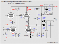
OK, this has been asked ad nauseum, but wanna make sure I don't fry a 6H30.
What I have on the 6H30 Output Tube:
V at Plate - Top Section - 204vdc
I of tube 24ma
V at Plate - Bottom Section - 102vdc
So 204 * .024, I get 4.89 watts and max plate dissipation is 4 watts (can be pushed to 6 says BAT)
Now since tubes are stacked, I am to use 1/2 B+ when figuring the plate dissipation, so top plate is 204vdc, bottom plate is 102vdc, 1/2 (204) * .024 and get 2.44 watts.
Now Andy Pairo asked this a while back and indicated the B+ should not be halved as the plate current is same in both sections of tube...
http://www.diyaudio.com/forums/tubes-valves/94217-e88cc-dissipation-aikido.html
As far as I see it, this would be correct, as the top section dissipation (with total voltage across section - in other words, subtracting the cathode voltage from plate voltage) is (204-102)* .024 and bottom section dissipation is (102 - 0)* .024 = 4.89 watts total in my case.
And to make this thread even more annoying, look at the following from Tubecad, where current is 40ma with a top plate of 150vdc giving 6 watts dissipation on a 6H30 if we don't half the top plate voltage....
What gives?? Driving me nuts. Seems like quite a few voltage / current selections in the Aikido manual also push / exceed the tube dissipation limits (if top plate voltage is not halved)...
The input tube is a 6N1P at 204vdc and 5ma, not that this matters to my question...
Attachments
Last edited:
Replace those tubes with resistors of the same value. Then it's obvious that each resistor get half B+ and will dissipate half B+ multiplied by the idle current.
Edit: then it's a matter of peeking at the spec sheet and check the max dissipation PER SECTION. Spec sheet usually states dissipation for each plate, not in total. This should make sense if the tube in question is dissimilar triodes or triode-pentode in one bottle.
Edit: then it's a matter of peeking at the spec sheet and check the max dissipation PER SECTION. Spec sheet usually states dissipation for each plate, not in total. This should make sense if the tube in question is dissimilar triodes or triode-pentode in one bottle.
Last edited:
Whoops, Sorry, looks like I should have done a little more homework....
6H30 Center design points:
1.Heater voltage………………………………….6.0-6.6 V
2.Maximum plate voltage..………………………250V
3.Maximum plate voltage for closed tube……….1050V
4.Maximum grid voltage in pulse mode t<=100uS…-50V
5.Maximum heater-cathode voltage……………..400V
6.Maximum pulse current for each triode……….6A
7.Maximum cathode current for each triode…….100 mA
8.Maximum plate dissipation for each triode……4 Watts
9.Maximum grid dissipation for each triode…….0.4 Watts
10.Maximum grid resistance…………………….300 kOhm
11.Maximum bulb temperature………………….250 degrees C
I did not look up the 6H30 specs, but usually the maximum allowed power for both triodes is not twice that of one section; some 50% more (heat inside glass etc.). This particularly for plate dissipations of several watt per triode. It varies somewhat from one double triode to the next.
- Status
- This old topic is closed. If you want to reopen this topic, contact a moderator using the "Report Post" button.
- Home
- Amplifiers
- Tubes / Valves
- No not Again...Aikido Plate dissipation question
