at pin 8 of V1= 5ar4, theres a big 10 uf-600v caps
theres in paralell with c3 40uF-440v.) one of the big gray caps of 20uf-440v
Are you saying that there is a 10uF 600V from 5AR4 pin 8 to ground?
If yes, that means the schematic is wrong, and it's not a choke input supply.
--
Attachments
Last edited:
Going on the assumption that yes there is a 10uF cap from 5AR4 pin 8 to ground....
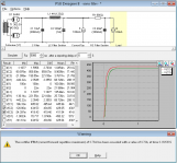
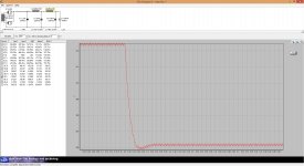
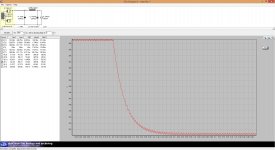
I ran a PSUD2 sim to see what the power supply looks like. If it is what I think it is, then the picture on the left is what I got. Note the warning that pops up that the peak current capability of the 5AR4 has been exceeded. Those tubes are being run right on the edge.
If we add a series 47 ohm 5W wirewound resistor between 5AR4 pin 8 and the 10uF cap, we get the results in the picture on the right. You'll lose about 6V off the B+. The AC ripple at the 100mA current tap is only 13.3 millivolts (after a 3 second delay). Not bad!
If that's correct, then you could probably reduce that series resistor to 22 ohms.
I may be doing something wrong in PSUD2, so if you see any mistakes, please point them out. Learn, learn, learn...
I hope this helps.
Attachments
Last edited:
yes exactlyAre you saying that there is a 10uF 600V from 5AR4 pin 8 to ground?
If yes, that means the schematic is wrong, and it's not a choke input supply.
--
I'll bet the voltage measurements on the schematic are wrong too. Can you take voltage measurements and post them here? It would be great to get measurements from:
- 5AR4 pin 8
- 100uF 440V cap
- 40uF 440V cap
- DC volts at pins 2 and 7 of the 6B4G's
- pin 3 of each 6B4G
- pins 1 and 6 of all four 6GU7 sections
- pins 3 and 8 of all four 6GU7 sections
- 5AR4 pin 8
- 100uF 440V cap
- 40uF 440V cap
- DC volts at pins 2 and 7 of the 6B4G's
- pin 3 of each 6B4G
- pins 1 and 6 of all four 6GU7 sections
- pins 3 and 8 of all four 6GU7 sections
the voltage are all exact and were taken recently.I'll bet the voltage measurements on the schematic are wrong too. Can you take voltage measurements and post them here? It would be great to get measurements from:
- 5AR4 pin 8
- 100uF 440V cap
- 40uF 440V cap
- DC volts at pins 2 and 7 of the 6B4G's
- pin 3 of each 6B4G
- pins 1 and 6 of all four 6GU7 sections
- pins 3 and 8 of all four 6GU7 sections
Thanks Scott17 for setting me straight. That helps a lot.
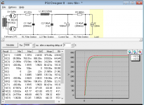
Assuming the two 6B4G's are drawing 122mA, the second stage draws 16.67mA and the first stage draws 15mA, then I get the following voltages:
B+ to the OPT center tap = 413V (that's too high!!)
Ripple on the B+ to the 6B4G's = 192mV
B+ to the second stage = 392V, ripple = 17mV
B+ to the first stage = 382V, ripple = 11mV
(see attached screenshot)
_______________________________________________
If that's correct, then the 6B4G's are seeing about +410V on their plates, with a cathode bias of +60V, so plate-to-cathode voltage of +350V. That's 50V too much, and will cause the vintage 6B4G's to fail prematurely.
Also, the plate dissipation of each 6B4G would be a whopping 21 watts (!!). That's 6W over the 15W max dissipation spec for the tube. They'd be running way too hot.
Are you sure the voltages on the schematic are correct?
If the voltages are correct, then triode-wired EL34's would be a better choice for this particular setup. They can take the higher voltage and are good for 25W max plate dissipation, so safe there too.
--
Attachments
the voltage are all exact and were taken recently.
OK, thanks. I guess that answers that question!
The only thing that pops out at me is the operating points of the 6B4G's.
- If the voltage at the 6B4G plates is about +360V, and the voltage at the cathodes is +60V, then the plate-to-cathode voltage is at the 6B4G's limit of +300V.
- 60V across 500R means the plate current of each 6B4G is 60mA.
- 300V * .06A = 18W plate dissipation. That's 3W over the 6B4G's published limit of 15W. If those are Sovtek 6B4G's, then I think they can take it. If they're old USA 6B4G's, then I'm not sure how long they'll last pushed over the limit like that.
Well, that's all I got.
_____________________________________
PS - Can a DN2540 be used with only 9V going across the device? The 6GU7 LTP/driver needs to swing 120Vpk-pk, so I was thinking the tail will need a negative supply to work well.
Also, a B+ of only +340V makes it tough to DC-couple the first and second stages and still get enough swing out of the second stage. Here's another case where triode-wired EL34 outputs would make life a lot easier. EL34-triode would need about half the drive voltage compared to 6B4G. That would make things a lot easier for that LTP/driver stage.
--
Last edited:
I'm at a loss as well regarding the measured voltages and the PSUD2 modeled voltages.
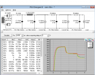
Could it be the first cap is out of tolerance? I notice that changing the 1st cap to 4.7uF brings the B+ down considerably, to right around 386V. That's using 4H @ 123R, again we are guessing at the inductance.
Could it be the first cap is out of tolerance? I notice that changing the 1st cap to 4.7uF brings the B+ down considerably, to right around 386V. That's using 4H @ 123R, again we are guessing at the inductance.
I saw that the line voltage was 110V so I changed the PT parameters to reflect that.
Where are you located youknowyou?
Changing the config to a CLCLC lowish DCR brings the voltage way down, maybe too low, but the settling time is pretty good.
Leaving everything else as is and just changing the rectifier to a 5R4 brings the voltage down, but the settling time, not so good.
At this point, I'm kind of with you rongon, that's about all I got too.
Attachments
Here's a wacky idea.
Take away the bypass capacitor C6 from across R13 and R14. Just remove it. Then listen to the amp. Does the bass sound more in control? Measure the bass response with and without C6 in place. Any difference?
--
PS - You might consider changing R14 from 1k to 1500 ohms. That should reduce the current through the 6B4G's, which would get them running a bit cooler, and not so far over their plate dissipation limit.
Last edited:
FWIW...
If you wrap negative feedback around the amp, you'll want a triode with higher gain and high transconductance in that first stage.
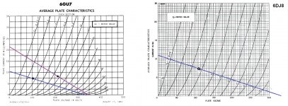
Looking at the characteristic curves for types 6GU7 and 6DJ8 (attached graphic), you can see that in the first stage of the amp, a 6DJ8 should drop right in and bias up properly.
6DJ8 amplification factor is about 30, compared to about 15 for the 6GU7.
A 6GU7 with 100V on the plate and 8mA of plate current will have transconductance of about 3.5mA/V. A 6DJ8 at those same conditions will have transconductance of about 8.5mA/V.
Don't try to use a 6DJ8 in the second stage, as the plate voltage is too high there (the 6DJ8's limit is 150V).
You can substitute types 6N23P, 6922 or ECC88 instead of 6DJ8.
(In the attached graphic, the purple line represents the loadline for the second stage LTP. The blue line represents the loadline for the first, input stage.)
--
If you wrap negative feedback around the amp, you'll want a triode with higher gain and high transconductance in that first stage.
Looking at the characteristic curves for types 6GU7 and 6DJ8 (attached graphic), you can see that in the first stage of the amp, a 6DJ8 should drop right in and bias up properly.
6DJ8 amplification factor is about 30, compared to about 15 for the 6GU7.
A 6GU7 with 100V on the plate and 8mA of plate current will have transconductance of about 3.5mA/V. A 6DJ8 at those same conditions will have transconductance of about 8.5mA/V.
Don't try to use a 6DJ8 in the second stage, as the plate voltage is too high there (the 6DJ8's limit is 150V).
You can substitute types 6N23P, 6922 or ECC88 instead of 6DJ8.
(In the attached graphic, the purple line represents the loadline for the second stage LTP. The blue line represents the loadline for the first, input stage.)
--
Attachments
Last edited:
If that's correct, then the 6B4G's are seeing about +410V on their plates, with a cathode bias of +60V, so plate-to-cathode voltage of +350V. That's 50V too much, and will cause the vintage 6B4G's to fail prematurely.
Also, the plate dissipation of each 6B4G would be a whopping 21 watts (!!). That's 6W over the 15W max dissipation spec for the tube. They'd be running way too hot.
looks like it, be mindfull of red plates, some tubes can take more, some just enough, so back down the bias at first sign of red plating...
I just thought of pointing out that even if changing the input valve to ECC88, double the gain only means 3db available for feedback, not nearly enough to help things...
I also dont like the LM317 as a CCS in that application, either have a decent CCS or a plain resistor is OK too
I also dont like the LM317 as a CCS in that application, either have a decent CCS or a plain resistor is OK too
I just thought of pointing out that even if changing the input valve to ECC88, double the gain only means 3db available for feedback, not nearly enough to help things...
I also dont like the LM317 as a CCS in that application, either have a decent CCS or a plain resistor is OK too
Thanks for jumping in.
")
Re: Enough gain for NFB -- Changing the output tubes to triode wired EL34's would help things. Probably only about 30V peak needed to drive them to full power (<10W). Also, changing the first stage to a 12AT7 (with a CCS in the plate) might help too. The combination of a high-mu triode in the first stage and EL34 outputs would allow room for some NFB.
Re: LM317 tail -- A plain resistor in that spot would be only 680 to 750 ohms. That's not nearly enough for a long tail, is it? It wouldn't be hard to try it out. Just replace the LM317 with a 750R 1W resistor.
Also, what device can be used as a better CCS in that spot, with only 9 or 10V across it and about 15mA going through it? Would a single DN2540 work well enough there, with that low a voltage?
i think not enough open loop gain for feedback.
6gu7 has mu of about 17, the output tubes are triodes...
Thanks for weighing in. Sounds like another vote for switching to EL34 outputs, right? Half the drive requirement means another 3dB of NFB possible, for a total of -6dB. That would be just barely enough, correct? (Still not optimal, I know...)
Mullard 520 without global feedback is not a good idea at all. This amp must have negative feedback from input tube to the secondary of output transformer.
Yes, and the power transformer is capable of higher voltage too, so again, EL34's would work better than 6B4G's.
Another possibility would be to add a negative supply so that the LTP/phase splitter could be moved to the first stage, and the second stage used as a differential driver with push-pull inputs. Something along these lines (but not exactly):
An externally hosted image should be here but it was not working when we last tested it.
Then there's this possibility, a Williamson-style circuit (apparently designed for Albert Einstein):
As a matter of fact, that last circuit would be a good one to try. All that's necessary is to adapt it for 6GU7's, which is easy enough to do. No additional negative supply needed for this one.
I think the limitation here is trying to use 6B4G outputs in a simple circuit with this combination of power xfmr and OPT. I'd prefer to see a B+ of about +450 for the driver stages and B+ of about +325V for the 6B4G's. But that would require separate power xfmrs for driver stage and output stage.
--
Last edited:
Well , actually a vote for 6V6. At ~300V A-K, right on the limit
Then again, the 6B4G is kinda special, a pity to swap it out. So the Einstein wins for me.
About the tail of the second stage. It would work very nice with a ~12 KOhm, and has to be changed to self-biased (a ~680R on top of the tail)
Then again, the 6B4G is kinda special, a pity to swap it out. So the Einstein wins for me.
About the tail of the second stage. It would work very nice with a ~12 KOhm, and has to be changed to self-biased (a ~680R on top of the tail)
Well , actually a vote for 6V6. At ~300V A-K, right on the limit
Still, the same problem as 6B4G, and...
Then again, the 6B4G is kinda special, a pity to swap it out. So the Einstein wins for me.
Yup, I agree!
About the tail of the second stage. It would work very nice with a ~12 KOhm, and has to be changed to self-biased (a ~680R on top of the tail)
Well, the problem is that a 10k resistor with 10mA going through it would need to drop 100V, and the B+ to that LTP stage is only +345V. That leaves only 245V for both the triodes and their plate and cathode resistors. Since 6GU7 has internal plate impedance of 5500 ohms or so, the plate load resistors need to be about 12k minimum. The bias needs to be in the -9V area to get enough swing for driving the 6B4G's to full power. So that's 72V dropped across the plate load, 9V dropped across the cathode resistor, leaving a plate voltage for the tube of only +165V. That means the bias will be down around -6V. 6V peak input times gain of about 8 equals only about 48V peak output. We need 60V peak, at least.
It now looks like the tube type will need to be changed to something with much higher mu, which means higher internal plate impedance. That doesn't usually work so well driving big power triodes with their high-ish input capacitance. Of course the way around that is to add MOSFET followers, but then the amp is no longer very simple...
So, my feeling is that either a negative supply has to be added for the LTP stage, or the whole thing should be changed over to something more Williamson-like (e.g., the Einstein amp). So in the end, for this particular case...
I like the Williamson-Einstein idea too.
--
Last edited:
- Status
- This old topic is closed. If you want to reopen this topic, contact a moderator using the "Report Post" button.
- Home
- Amplifiers
- Tubes / Valves
- How to improve this 6B4G push-pull circuit