Are you sure that adding NFB to the williamson circuit will result in better sound? Ive been told that the Williamson circuit sounds better without NFB...
Mr. Williamson designed his PP Kt 66 amp with -20dB feedback. You don't need to worry about the Williamson as your circuit does not resemble it.
Your amp more resembles the Mullard 5-20 with the front end tube paralleled and a CCS in the tail of the long tail pair driver tubes. It would not be hard to improve what you have. With a decent power supply and the Dynaco output transformers it is an audio experimentor's work horse.
I will get the choke you recommend (Edcor CXC100-7H-150mA), as im sure the choke I have is not even close to ideal
Don't rush out and buy that choke just yet. If you can provide the DCR information I requested in a previous post there may be a better alternative.
Haven't we seen this amp before?
http://www.diyaudio.com/forums/tubes-valves/190089-i-think-i-made-mistake-5.html
jeff
http://www.diyaudio.com/forums/tubes-valves/190089-i-think-i-made-mistake-5.html
jeff
yes, thats me! You have a good memory! Simply, I have tried to reopen the murphythecat account without any response from the mod, so I opened a new account.Haven't we seen this amp before?
http://www.diyaudio.com/forums/tubes-valves/190089-i-think-i-made-mistake-5.html
jeff
I'll measure the choke and report back.
Haven't we seen this amp before?
http://www.diyaudio.com/forums/tubes-valves/190089-i-think-i-made-mistake-5.html
jeff
Yup, that's the one. I see that tomchr took a stab at changing some things back then. If anyone should know what might work well, he certainly would.
As was correctly pointed out, that circuit is not a Williamson. It is close to a Mullard 5-20. It's even closer to something like an EICO HF-87.
6GU7 is almost exactly like 12BH7A, but with 6.3V heaters instead of 12.6V.
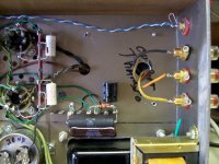
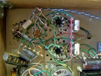
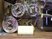
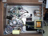
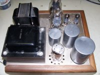
Re: Hum and murky sound -- Are we sure the grounding is done reasonably well? A photo of the layout and wiring would be very helpful. It's even possible that the power transformer and/or choke are coupling hum into the OPT or audio circuits.
If that's not it, then possibly the problem is trying to marry 6B4G's with that particular power transformer and choke combination. Maybe if you used a 5R4 rectifier and a power supply choke with a higher DCR (say 100 to 120 ohms), and let that drop 50 volts or so, then a small value film cap could be put right after the rectifier to lift the B+ voltage back up to the desired +370V. That way you could use a higher inductance choke, which should filter out more ripple on the supply. That can't help but improve things.
I really wish we knew exactly what power transformer that is.
And, we don't even know if a larger choke will fit on the chassis or not.
If the first stage could be DC-coupled to the LTP (2nd stage) then maybe a DN2540 CCS could be put in the tail. That will need at least 20V across it to work at its best, right? Either that or add a -25V DC supply for a DN2540 tail CCS.
Or even mo' better... Why not use that twin triode in the first stage to make an LTP phase splitter with a constant current sink (CCS) in its tail? Maybe a 12AT7 could go there, a la Eli Duttman. Or just use the two 6GU7's you already have there. That 1st stage LTP could be DC-coupled to the second stage differential pair. You'll get better push-pull balance and lower distortion that way, at the expense of quite a bit more complication. That first stage LTP will need a negative supply to feed a CCS in its tail. Then the 2nd stage can have a long tail (CCS) or just a shared cathode bias resistor, as in the Williamson's driver pair.
Those Reference 3a speakers are supposed to be tube amp-friendly, with the woofer running all the way up with no choke, and the tweeter coming in with a single cap as its high pass filter. I don't know if the crossover has impedance EQ, notch filters, baffle step compensation and all that, and I don't know what its impedance curve is like. I've never heard the speakers.
At any rate, we need more information for sure. A picture of the wiring and layout would absolutely help matters.
--
Yes, that's probably too high. 6B4G is a 2A3 with a 6.3V filament in an octal base. Maximum plate to cathode voltage is 300V. Typical operation is listed as 250V plate to cathode.
youknowyou has the B+ at about 367V, with 60V at the cathodes, so V plate-cathode is about 300V (the maximum).
--
youknowyou has the B+ at about 367V, with 60V at the cathodes, so V plate-cathode is about 300V (the maximum).
--
L1 = 123 ohms
Well, then it's not the Dyna C354 choke. That one's only about 2H, and has a DCR of about 60R (IIRC).
Can you take a picture of the choke and let us see what it looks like? Or post measurements? Is it mounted inside the chassis, or is it on top?
--
I took a wild guess at a power supply model in PSUD2. I guessed that the pwr transformer would be about 850VCT unloaded (figuring on +380V from a choke input supply with a 5AR4 rectifier).
Using a 5R4GB rectifier to a 1uF reservoir capacitor, 7H choke with DCR = 123R, and a 100uF filter capacitor, I got B+ of +356V with about 1.2V AC ripple.
--
Using a 5R4GB rectifier to a 1uF reservoir capacitor, 7H choke with DCR = 123R, and a 100uF filter capacitor, I got B+ of +356V with about 1.2V AC ripple.
--
This configuration may be an option, but I'm just guessing concerning the PT DCR.
Maybe the B+ is too high? I'm not familiar with the 6B4G parameters.
Its like an indirectly heated 2A3.
According to TungSol, 6B4G is directly heated.
http://frank.pocnet.net/sheets/127/6/6B4G.pdf

6A3 is the four-pin version.
http://frank.pocnet.net/sheets/127/6/6A3.pdf
6A5G was the indirectly heated version, but that's a rarity.
http://frank.pocnet.net/sheets/121/6/6A5G.pdf
There is another rare form of 6B4G that is actually a 6AV5GA, internally triode wired. It was sold by Sylvania and Philips ECG. That was a weird one that still pops up from time to time.
--
http://frank.pocnet.net/sheets/127/6/6B4G.pdf
6A3 is the four-pin version.
http://frank.pocnet.net/sheets/127/6/6A3.pdf
6A5G was the indirectly heated version, but that's a rarity.
http://frank.pocnet.net/sheets/121/6/6A5G.pdf
There is another rare form of 6B4G that is actually a 6AV5GA, internally triode wired. It was sold by Sylvania and Philips ECG. That was a weird one that still pops up from time to time.
An externally hosted image should be here but it was not working when we last tested it.
--
Last edited:
Will sure do and the pictures are coming soon.Thanks.
It sure would be helpful if the OP could measure the primary and secondary resistance of the power transformer he has.
He could also measure the off-load AC voltage while the 5AR4 is removed across pins 6 & 4.
hang on guys
thanks
Thanks.
He could also measure the off-load AC voltage while the 5AR4 is removed across pins 6 & 4.
Actually, that might be enough. We know the current load, and we know the voltage that results. If we knew what the off-load AC voltage was from the secondary, then PSUD2 could be used to figure out approximately what the resistances of the windings are. So if we could just get that off-load voltage, that would be a great start, and would require no disassembly of the amp. Thanks for the idea!
--
BTW, which version 6B4G's are in your amp?
??
Or...
--
Or...
An externally hosted image should be here but it was not working when we last tested it.
??--
No disassembly required, just unplug the 5AR4, and the primary can be measure on the ac plug with the power switch on. Unplugged from AC voltage of course.
Actually, that might be enough. We know the current load, and we know the voltage that results. If we knew what the off-load AC voltage was from the secondary, then PSUD2 could be used to figure out approximately what the resistances of the windings are. So if we could just get that off-load voltage, that would be a great start, and would require no disassembly of the amp. Thanks for the idea!
--
the power transformer
Primary: 2.4 ohms
Secondairy: 22 ohms - tension output 725 Vrms.
Primary: 2.4 ohms
Secondairy: 22 ohms - tension output 725 Vrms.
Attachments
- Status
- This old topic is closed. If you want to reopen this topic, contact a moderator using the "Report Post" button.
- Home
- Amplifiers
- Tubes / Valves
- How to improve this 6B4G push-pull circuit