Hi all,
It's been a while since i last posted here. I've been playing with tube amps for some time now but i seem to have hit a bit of a brick wall in my quest for audio heaven. The problem i have is this...:-
I've been trying to avoid using commercial Output transformers due to their cost and the fact that i like to be individual and keeps things diy. In pursuit of this i have been using mains torriods in push pull with remarkable success. They perform flawlessly from 50Hz to around 100kHz. The efficiency of these off the shelf mains torroids is good along with phase angle. So whats the problem i hear you ask??
The issue is after a few years playing with mains torroids i thought it was about time i built a finished amp. to this end i ordered a commercial audio transformer thinking all would be well, or at least a great improvment on my mains torroids. My mains torroids dont really go much lower than 40Hz on full power unless i use very large ( over 400VA )torroids. Upon trying the commercial audio unit i found that it also will not put out full power below 40Hz. It can only deliver about 1 watt at 20Hz before saturation. An improvment on my mains torroid which can only put out around 100mW at this frequency but still rarther poor for a comercial transformer rated at 40W audio. The commercial units high end responce dies off much sooner than the mains power toroids but its phase angles are better.
What i'm wondering is how much power at low frequencies below 50Hz should i expect? Am i really expecting too much to get full power at 20Hz and below or is this a common limitation of tube amps?? What is your real measured full power lower limits before distortion/saturation??
Mine are as follows:-
Off the shelf 100VA power torriod:-
50Hz/14Wrms 40Hz/15Wrms 30Hz/9Wrms 20Hz/2Wrms 10Hz/100mWrms

Quality audio torroid rated 40W
50Hz/15Wrms 40Hz/15Wrms 30Hz/15Wrms 20Hz/8Wrms 10Hz/1Wrms
Leigh
It's been a while since i last posted here. I've been playing with tube amps for some time now but i seem to have hit a bit of a brick wall in my quest for audio heaven. The problem i have is this...:-
I've been trying to avoid using commercial Output transformers due to their cost and the fact that i like to be individual and keeps things diy. In pursuit of this i have been using mains torriods in push pull with remarkable success. They perform flawlessly from 50Hz to around 100kHz. The efficiency of these off the shelf mains torroids is good along with phase angle. So whats the problem i hear you ask??
The issue is after a few years playing with mains torroids i thought it was about time i built a finished amp. to this end i ordered a commercial audio transformer thinking all would be well, or at least a great improvment on my mains torroids. My mains torroids dont really go much lower than 40Hz on full power unless i use very large ( over 400VA )torroids. Upon trying the commercial audio unit i found that it also will not put out full power below 40Hz. It can only deliver about 1 watt at 20Hz before saturation. An improvment on my mains torroid which can only put out around 100mW at this frequency but still rarther poor for a comercial transformer rated at 40W audio. The commercial units high end responce dies off much sooner than the mains power toroids but its phase angles are better.
What i'm wondering is how much power at low frequencies below 50Hz should i expect? Am i really expecting too much to get full power at 20Hz and below or is this a common limitation of tube amps?? What is your real measured full power lower limits before distortion/saturation??
Mine are as follows:-
Off the shelf 100VA power torriod:-
50Hz/14Wrms 40Hz/15Wrms 30Hz/9Wrms 20Hz/2Wrms 10Hz/100mWrms
Quality audio torroid rated 40W
50Hz/15Wrms 40Hz/15Wrms 30Hz/15Wrms 20Hz/8Wrms 10Hz/1Wrms
Leigh
LF power through an OPT requires a large OPT with high inductance. HF stability pulls you in the other direction so all audio OPT are a compromise. That is why valve amps used to have two frequency ranges quoted: one at full power (or nearly so), and one at low power.
If you need LF power then you need solid-state.
If you need LF power then you need solid-state.
As DF96 said, it is not the size of the transformer per se, but its inductance that hampers your LF response. A 400VA model will be no better than a 50VA model if they have the same inductance (and they probably will be similar). They are all designed to run close to saturation at rated mains voltage and frequency (e.g. 240V 50Hz), regardless of size. That is the convenience of designing mains transformers: you only have one frequency and voltage to worry about! Audio transformers don't have this luxury.
If you want to run half the frequency through them (25Hz) you need to half the voltage (120V) for the transformer to run at max flux density. Any more and it will probably saturate. How much power that gives you, depends on the primary impedance: P = V^2/R.
The primary inductance is likely to be low (20H maybe?), which means you can't be too ambitious about the primary impedance (parallel combination of inductance and reflected load). You will therefore need a low impedance output stage in order to drive it successfully (RL high-pass filter, remember). This may in fact be possible with a triode output stage. If you think you can get the primary impedance around 1k*, say, then the max power will be 14.4W, but more like 12W with losses. Applying exactly the same logic but down to 20Hz, you would have to limit your voltage to 240*(20/50Hz) = 96Vrms, reducing the power output to 9.2W, or maybe 8W realistically.
But if you could tolerate a primary impedance of 500 ohms, say, (and can find valve to drive it) then you could handle double the audio power. So it depends on your output stage, transformer inductance, and the turns ratios you can get your hands on. Obviously the VA rating needs to be at least equal to the audio output power, too.
*For example, a 20V transformer has an ideal turns ratio of 240/20 = 12, but probably more like 10 in practice (because it will be deliberately overwound a bit).
If you hook it up to an 8 ohm speaker, the reflected load will be 8*10^2 = 800 ohms.
If the primary inductance is 20H, then the inductive reactance at 20Hz is 2513 ohms.
The total primary impedance is the parallel combination and comes out at 762 ohms; not too bad compared to the ideal 800 ohms (which is why I chose a 20V transformer!), so the frequency response should be relatively flat.
If the max drive voltage is 96Vrms, the output power is 96^2/762 = 12W. Call it 10W to allow for losses.
So, can you design a valve output stage that can drive 10W into 800 ohms? Maybe...
If you want 20H - 20kHz razor flat with low distortion, it ain't going to happen with a mains transformer. But if you want 20Hz - 10kHz, "more or less flat" with "some distortion" then I think it can be done.
Last edited:
If you need LF power then you need solid-state.
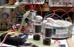
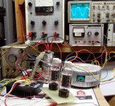
I have breadboarded a tube audio amp that happily cranks out 150 watts at 20 Hz with under 1% distortion using toroidal OPT's. The -3db points at 100 watts were 7 Hz, saturation limited, and 67 KHz distortion and tube current limited. These were however NOT cheap OPT's, they were Plitrons rated for 400 watts at 20 Hz.
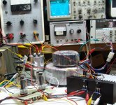
The third picture shows a dumpster toroid sitting on top of the Plitron. This amp breadboard is actually a hybrid using tubes (6W6) and mosfets in a "Darlington" configuration as output devices. These toroids were obtained from a dumpster behind an industrial machine shop. Given the other stuff in the trash that day, they were used in stepper motor power supplies. I got about 4 or 5 of them. They will make about 50 watts down to 40 Hz and about 15 watts at 20 Hz.
Many people will tell you to balance the idle current through a P-P stage for lowest distortion. This is NOT the case. There is no such thing as a perfectly balanced OPT. Usually some imbalance is required in the tubes to offset the imbalance in the OPT. Even the big Plitrons need some offset. This is also true for conventional EI OPT's. Measure the distortion at 20 or 40 Hz then tweak the cathode currents to minimize it.
You will also find that the distortion changes with power level and frequency. Matched Gm tubes helps, but they won't stay matched forever. AC imbalance in the driver circuit is key here. Add a pot to allow for a small imbalance, and maybe even a small trimmer cap to tweak the HF.
Attachments
So what your saying is that a 500VA transformer of the same type as the 100VA transformer i'm using now won't make much difference?
Based on that assumption one is forced to declaire tube amps dont do bass and i should give up??
I find it hard to belive. Have all previous tube amps been sold without the ability to reproduce subsonic bass and vibration??
I must say, i'm shocked. This must be wrong, or is it that the more quality driven manufacturers use giant Xformers the size of fridges??
Leigh
P.S I'm near you, i'm in Accy
Last edited:
Yes, because they both probably have similar primary inductance. The only reason the one is bigger than the other is that it uses fatter wire to handle more current, which has nothing to do with inductance.So what your saying is that a 500VA transformer of the same type as the 100VA transformer i'm using now won't make much difference?
No, but they used proper audio transformers, not mains transformer!I find it hard to belive. Have all previous tube amps been sold without the ability to reproduce subsonic bass and vibration??
It's not the size of the transformer, it's the primary inductance! A proper audio transformer will have inductance of perhaps 100 to 300 henrys, so they can maintain a higher primary impedance at low frequencies and take higher drive voltage to acheive the desired power.This must be wrong, or is it that the more quality driven manufacturers use giant Xformers the size of fridges??
Mains transformer just aren't designed for that, because they're always used at 240V 50Hz. You can't expect to drive one with 300Vrms at 20Hz without meltdown!
Last edited:
Hmmm, I'm confused because the real audio toroid i bought performs nearly the same as the standard mains toroid, both have the same weight and look to be roughly the same dimensions. I thought this was all about core material saturation and not purley based on primary inductance.
Leigh
Leigh
The numbers you posted look very different to me... your audio OP is delivering the same power all the way down to 30Hz, and at 20Hz the power is about half the midband, indicating a -3dB point somewhere around 20Hz. Not bad. Unlike the mains toroid which is already struggling at 30Hz.Hmmm, I'm confused because the real audio toroid i bought performs nearly the same as the standard mains toroid,
I suspect you haven't really made a fair comparison. Maybe you could post more details about your test setup, and especially the turns ratios of the two transformers (I seriously doubt they are the same).
Last edited:
Here are the data sheets for the two toroids i tested. The mains toroid i used is 100VA 12 dual primary and secondry, a 20:1 ratio. The toroids were tested on a test setup consisting two EL34's wired push pull on 300V B+, 76mA each, balanced to within 1mA. The load on the secondry was a resistive 8R. The testsignals pure sine, all test measurments in watts RMS. The mains toroid was wired pushpull on its dual primaries, the load connected accross one of the 12V secondries. The Audio toroid did not use its UL taps. All tests carried out with the tubes in Pentode mode. The output waveforms were monitored on the scope ( open loop of course ) and power and frequency adjusted until visible distortion was detected. Not exactly scientific but the results were i thought a fair comparison.
Leigh
Leigh
Attachments
So the audio toroid had a primary impedance of 3.5k. I don't know why it didn't deliver 15W at 20Hz; I would certainly expect it to with those specs.
But the mains tranny had a primary impedance of probably around 2.6k in parallel with whatever inductance it has. Probably not enough to hold up 2.6k down to 20Hz. Let's say it amounts to 2k. You reported 2W at 20Hz, which into 2k is 63Vrms, about two thirds saturation voltage. This sound reasonable to me, as distortion will be visible before "full" saturation is reached. And with a load like that it could have been valve distortion just as much as transformer distortion that you were seeing.
What kind of distortion did you see? Clipping or crossover?
Last edited:
The distortion was similar but not quite the same as crossover kinks appearing, no clipping at all. You could hear it too. A test speaker was connected all the time through a 1K resistor, when the distortion occurrs you can hear it as well as see it. I thought i'd have more power. Especially when the B+ is quite low at 300v. May i expect too much, or maybe i should just get hold of a 1KVA 9V toroid and run the tests again LOL
The primary inductance is one of the main factors that determines "how low can you go" another is the magnetic capability of the core. Both are taken into careful consideration when designing an audio OPT. A mains transformer just needs to have enough to avoid excessive idle current at the mains frequency.
Distributed winding capacitance determines the other end of the spectrum. Too much capacitance shunts off all the high frequencies, but this is not a consideration for mains use.
Insufficient inductance appears as a resistance across the transformer that gets lower with decreasing frequency. Excess capacitance appears as a resistance across the transformer that gets lower with increasing frequency. Both tend to short out the audio power at the frequency extremes.
My experience with mains toroids as OPT's has revealed a very wide variation even among identical transformers. There are things you can do to make mains toroids work better. My previous post detailed tweaking the bias currents and drive levels. You can also mitigate the insufficient inductance and excess capacitance by driving the transformer with the lowest possible source impedance. Pure pentode without any feedback is the absolute worst case. Triode mode works better since the tube's internal impedance is lower. Reducing the tubes impedance further with cathode feedback, plate to grid feedback, or both can make a crummy transformer work good.
Here are the data sheets for the two toroids i tested. The mains toroid i used is 100VA 12 dual primary and secondry, a 20:1 ratio. The toroids were tested on a test setup consisting two EL34's wired push pull on 300V B+, 76mA each, balanced to within 1mA. The load on the secondry was a resistive 8R. The testsignals pure sine, all test measurments in watts RMS. The mains toroid was wired pushpull on its dual primaries, the load connected accross one of the 12V secondries. The Audio toroid did not use its UL taps. All tests carried out with the tubes in Pentode mode. The output waveforms were monitored on the scope ( open loop of course ) and power and frequency adjusted until visible distortion was detected. Not exactly scientific but the results were i thought a fair comparison.
Leigh
Not really a good way to measure transformer performance. You should use a distortion free generator, not pentodes!
Anyway the Plitron datasheet states clearly that the power bandwidth starts at 27 Hz which means that at this frequency the transformer can handle 50% of the specified power (i.e. it can handle 20W). And this could be a "safe" value (i.e. still not too close to saturation).
Your 100VA supply transformer in theory should handle about 16W at 20Hz. It doesn't because for a number of reasons.
First, it has not got a gap and so any DC unbalance as small as 1 mA will take some non negligible amount of the available induction and inductance will decrease quite a lot approaching saturation (this is absolutely true for the Plitron as well). At least perfect balance is necessary if you want to take full advantage (in fact Van Der Veen uses a servo bias in his amps) or use a larger transformer.
Add to this that you are only using one secondary and the power loss will take some other power. If you try with the two secondaries in parallel you should be able to see some improvement. Anyway it has to be seen which is the real efficiency of you supply transformer. Have you measured the DC resistance of all windings? Usually cheap supply transformers are not that efficient.
Last, it is not a 100 VA transformer!
All this could explain why you can only manage 2 W at 20Hz instead of 16W (including the non negligible distortion of the output stage as the load is not the same as at 1KHz...).
Last edited:
Its interesting,
Bass and tube amps. SVT made a valve bass amp for guitar that could shake the room.
The Vellman with 8 EL34 connected to a set of Tannoy 611's could shake the room and your guts at ear splitting levels.
This is always assuming that there is nothing else stopping the OP Tx from reaching its maximum output (we assume there isn't) But on reflection bypass caps on OP tubes and chokes or other in PSU's can have a marked effect. (Back EMF is another issue)
Are you sure its the OPtx and not current available from the PSU?
There is always OTL..
If your looking at powering PA that's a different matter..
NB if you are looking at Church organ bass then you have to look for inspiration at things like REL.
Regards
M. Gregg
Last edited:
Its deffo not the supply, The HT is derived from a very substantial supply and is monitored. Its rock steady at 300V. I know the test setup is not ideal for testing transformers but i never intended to set out test transformers. I just thought i'd report my observations as they were not what i thought i'd see and ask what your transformers perform like at low frequencies. Different drive to the transformers does not effect this lower limit i am seeing as its the transformer saturating and not a lack of drive. Anyone ever tested their own creations?? If so what did you see under 50Hz? Personally i like Tublabs piltron toroids earlier in this thread. Now Thats a transfromer!
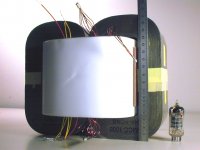
Well, depending on how much you want to spend, Monolith Magnetics makes some SUBSTANTIAL transformers. The OPTs for my 200WPC 833C SET amps weigh 62 lbs each. Here's a pic of the wound core before strapping and potting, with a metric ruler and ECC83 for comparison.
It's a Metglas amorphous double-C core, with teflon interwinding insulation and vari-lay winding. Specs from Monolith are 8Hz to 66kHz (-3dB) small signal. Full power saturation at 35Hz.
PS: The bass shakes the walls and floor even more than the 500WPC Class D amp I was using previously, and surprisingly, it's better defined as well!
Attachments
Last edited:
- Status
- This old topic is closed. If you want to reopen this topic, contact a moderator using the "Report Post" button.
- Home
- Amplifiers
- Tubes / Valves
- How low can you go...?