I have a pair of IPC AM-1027 theater monoblock amps that I am converting to be plug and play for domestic use. They are 6L6 PP using 6SL7 paraphase phase-splitter cap coupled to cathode followers in fixed bias mode. B+ about 375Vdc bias current 50mA each tube. All the voltage points are in the ballpark. I simplified the circuit so I bypassed the input transformer. Pretty straight forward circuit and I prefer to keep the stock circuit and no intention of modifying or "improving" it, just restore the amps in non-invasive way. Leaky coupling caps have been replaced and filter caps in B+ and negative bias supply also replaced. The only thing changed is the bias series resistor's value so the power tubes bias correctly. Both phases' level is the same so they are balanced in PP.
The amps have no hum and, with music, sounding good. But there's a buzz noise that's loud enough to be distracting. BOTH amps have the same noise issue. I checked most resistors and they are all within specs. When I removed the input tube, no noise, no hum, no buzz, so very likely the input 6SL7 is culprit. Changing tubes, same problem. Grounding the input grid, same problem. Here's the curious part, when I ground the grid of the inverter tube, the noise is gone, dead silent. Of course I lose half of the amp. Apparently the noise came from the signal feeding the second grid. I worked on amps using paraphase circuits before and never had this buzz problem before. I fixed another same pair for a friend about couple years ago with no issue but they are gone so I can't use them for troubleshooting or reference. There must be something that I'm not catching this time.
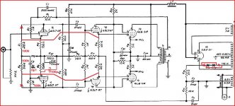
Below is a simplified schematic for troubleshooting. Currently the amps are wired as shown in the schematic. Thank you for any suggestion and help in advance.
The amps have no hum and, with music, sounding good. But there's a buzz noise that's loud enough to be distracting. BOTH amps have the same noise issue. I checked most resistors and they are all within specs. When I removed the input tube, no noise, no hum, no buzz, so very likely the input 6SL7 is culprit. Changing tubes, same problem. Grounding the input grid, same problem. Here's the curious part, when I ground the grid of the inverter tube, the noise is gone, dead silent. Of course I lose half of the amp. Apparently the noise came from the signal feeding the second grid. I worked on amps using paraphase circuits before and never had this buzz problem before. I fixed another same pair for a friend about couple years ago with no issue but they are gone so I can't use them for troubleshooting or reference. There must be something that I'm not catching this time.
Below is a simplified schematic for troubleshooting. Currently the amps are wired as shown in the schematic. Thank you for any suggestion and help in advance.
An externally hosted image should be here but it was not working when we last tested it.
Last edited:
I did a quick experiment by adding back the input transformer and using it to split phase. To preserve symmetry, I snipped out the negative feedback and also disconnected the paraphase circuit. Check picture below. No noise, dead quiet. So the noise is from what's feeding the phase-splitter's grid (pin 4 of V1).
Went back to the stock circuit and buzz noise again. Oscillation? I tried grid stopper at the 6SL7 grid, no luck. The buzzing noise is definitely from the phase splitter or combination of input and phase-splitter. This buzz is driving me nuts!
Quick test using input transformer as phase splitter:
Went back to the stock circuit and buzz noise again. Oscillation? I tried grid stopper at the 6SL7 grid, no luck. The buzzing noise is definitely from the phase splitter or combination of input and phase-splitter. This buzz is driving me nuts!
Quick test using input transformer as phase splitter:
An externally hosted image should be here but it was not working when we last tested it.
Is the feedback cap (C2?) picking up interference? What have you used for it?
C1 is the feedback cap but I snipped out the feedback network just to test and still has buzz. I can use shielded wire for the feedback wire from the secondary to the input cathode just to be safe. C2 is the input cap from the voltage divider in the paraphase circuit. I had NOS Blackcat caps at first and then I tried modern polypropylene cap, still same buzz. I wonder if I place the voltage divider network AFTER the coupling caps instead of the from the plates will make a difference.
Whenever I ground pin 4 of V1(6SL7) the noise goes away, either direct wire to ground or via a cap. When there's no AC in that grid, the noise goes away. Something is amiss in that region. I just can't nail down what's causing the buzz noise. When I only ground the input grid, pin 1, noise exist.
The circuit appears to be stable, when I put my hand over components there's no interference or antenna effect. The power supply is clean, no hum.
As a test, I even took out the FB (to avoid squealing oscillation) and swapped the phases, still same buzz.
What an ironically buzz-killed amp!
Thanks for the suggestion.
C2 is the one. If this cap is physically large it could pick up buzz. Try a small cap, or shield it with some grounded conductor.
I tried a smaller one and still buzzes. I did some socket cleaning and it improved a tiny smidgen.
Perhaps is it some grid current in the 1M resistor. See if taking out C2 has the same result as shorting the grid to ground (= no signal). If you put the divider resistors after the coupling C's you need to make those C's bigger.
Taking out the coupling cap results the same buzz and added some hum. It appears the 1M resistor is picking up noise. I put my finger close to it and it has antenna effect. Seems like the grid does not like having such high input impedance. Just for test, I decrease the value to 100k and the noise also decreases, and then down to 22K the buzz is almost inaudible. Of course this throws the balance and phase level out of whack. Most paraphase splitter circuits I worked with before are self bias so there's no need for a blocking cap. I would like to hear from other people's result using Floating Paraphase. Should I cap coupled and place the divider resistors at the grid so it's seeing a low value resistor to ground? Sort of cheating... No wonder it's quiet using input transformer because its DCR is very low.
I haven't tried placing the divider resistor after the caps but I have tried, just for yucks, taking the joint of R9 & R10 cap coupled back to the PI grid. No luck still buzz.
My head is full of buzzzzzzz.

A high impedance input node will always pick up some hum/buzz. Careful shielding may be the only answer, along with making sure that circuit node is as physically small as possible and as near the chassis as possible. You can't reduce the impedance by very much without loading the anode circuit too much.
Perhaps you could try it like this.I now it's not attacking the cause, only symptoms
By decoupling the cathode the gain goes up making the two divider resistors almost equal.
Thanks for the suggestion.
I'm thinking trying something like the below. I haven't wired it yet. I lose the self balancing effect of "floating paraphase" but I can adjust R? to balance level of two phases and R? will be a low resistor value that the grid likes. Taking the signal from one plate makes the load not equal for the two plates so R7 is increased and decoupling cap is added (maybe .22uf?). Is there a simpler trick to make the loads of two plates equal? Does it even matter? I have seen circuits, Scott 299B, using pentode and triode in paraphase so it's obvious two sides are not same impedance. I would prefer better symmetry, of course.
An externally hosted image should be here but it was not working when we last tested it.
(and two diodes the wrong way
Thanks for the correction. The drawing is from the stock schematic. I can't believe they made a mistake like that and I didn't catch that! The amps are factory wired correctly though. Imagine someone DIY'ing from the original drawing....
Last edited:
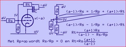
With this solution R1 and R2 are useless.The more than 1M at the anode makes little difference,the hole thing is now an aproximation (gain of a triodestage not precise)
Now the devider 1M/R? must do just the opposite of the gain of the triode,giving a total gain of x-1.The 6SL7 with the cathode only partly decoupled has a gain of ~25.So the R? = 1M/24.
The C2 (0µ01) is in series with the 1M ,need not increased.
Mona
Now the devider 1M/R? must do just the opposite of the gain of the triode,giving a total gain of x-1.The 6SL7 with the cathode only partly decoupled has a gain of ~25.So the R? = 1M/24.
The C2 (0µ01) is in series with the 1M ,need not increased.
Mona
With this solution R1 and R2 are useless.The more than 1M at the anode makes little difference, the whole thing is now an approximation (gain of a triode stage not precise) Now the divider 1M/R? must do just the opposite of the gain of the triode, giving a total gain of x-1. The 6SL7 with the cathode only partly decoupled has a gain of ~25. So the R? = 1M/24. The C2 (0µ01) is in series with the 1M, need not increase.
I think you meant R7 & R8. Anyway, I took them out. I use a fixed value of 33KΩ for R? and the levels are pretty matched and if I want to be more precise I guess I can use a 50KΩ variable resistor or pot to dial in to get exact equal level of both phases. I finally wired the whole thing as shown below and the noise is gone! The noise is so minute now that's inconsequential.
While the load of each phase is not equal but it's close enough. It's simplicity saves me the headache of changing and rearranging components as all the parts are on a turret board. This project is for a friend who is a vintage fetishist and is very stubborn about using modern parts so everything inside is vintage. Right now one can hardly tell the amp has been modified as all the rearranged wiring is tucked under the board. I am sure if I rewire the whole thing with modern more reliable parts (and add grid stoppers!) the noise will down even further but my speakers are 100dB sensitivity and I have to stick my ear close to the horn to hear a faint buzz which means it's plenty quiet for most speakers.
If they're my own amps I would use a bridging transformer to split the phase and have symmetrical feedback -- too bad the output transformer doesn't have a 4Ω tap as center tap so I can ground it. The stock input transformer is low impedance (600 Ω ?) primary so it would present a severe load for preamps, hence not using it. These amps really have potential for even higher performance. They sound great already as is.
As to the reason why the stock circuit buzzes, I speculate the signal does not like to go through a high value series resistor (470K Ω) before a load and the input grid resistor is also high impedance (1M Ω) which makes matter worse. But after the cap the signal still goes in series with a 1MΩ resistor though. Perhaps the grid's low resistance to ground lessens the noise significantly. Maybe this is just an individual case as there are so many floating paraphase circuits out there that nobody complains about. Right now, I just want to sit down and listen to some music before I rewire the other mono amp in order to play stereo!
This whole exorcism makes me rethink about the paraphase circuit. While subjectively I much prefer its sound over the LTP but its finicky nature makes me miss the split-load circuit. Hmm... I have another pair of 300B PP paraphase amps that also have buzz noise but it's self bias... anyway, that's for another noise hunting session in the future. Anyway, I learned a few things along the way so it's worth the effort.
Without your and DF96's help, I would still be hunting buzz right now so I appreciate all your help. Thanks fellow members!!

- - - - - - - - - - - - - - - - - - - - - - - - - - -
Just for yucks, this is something I might experiment in the future just so I can take advantage of the self balancing nature of floating paraphase.... if it doesn't buzz, of course.
I think adding an extra cap in the parts count isn't too bad. I wonder if R5 can be calculated to be low value... 
For now, I just wanna spin some records!
I have another pair of Simplex/IPC AM-1027 amps that are having similar buzz problem. This time in the below stock circuit, I notice there's positive grid voltage (approx 1.5VDC) at the phase inverter tube, pin 4, which theoretically should have zero volt. I replaced C2 with a new cap to make sure there's no leakage. I tried numerous tubes and they all have grid current. The noise level correspond to the size of the grid resistor, R5, after I changed it to a smaller value. I've never experienced this type of blatant grid current in a signal tube before. Any advice will be appreciated.

I think there's some design flaws in the circuitry. I'd do the following mods:
1 - Make R7 = R8.
2 - Omit R6, R12, C3A and connect both cathodes of the first tube.
3 - Make R22 = 1k8 and connect it to both cathodes.
4 - Disconnect R5 from ground and insert a 750 ohms resistor, maybe the old R12.
5 - Disconnect the bottom of R2 and return it to the R5/750 ohms connection.
6 - Swap both plates' lead to the output transformer.
This way you'll get a very well self-balancing Floating Paraphase PI.
Best regards!
Are you sure your DMM's reading is correct?
Sorry it was measured with the old cap which had some leakage. When I took the cap out, there is still some positive voltage at the grid, about 0.3VDC. I think the grid resistor is too large and built up grid current. I'm going to change the input grid resistor to 1M to see if it has the same effect. Perhaps 6SL7 is prone to grid current when grid resistor value is too large.
I think there's some design flaws in the circuitry. I'd do the following mods:
1 - Make R7 = R8.
2 - Omit R6, R12, C3A and connect both cathodes of the first tube.
3 - Make R22 = 1k8 and connect it to both cathodes.
4 - Disconnect R5 from ground and insert a 750 ohms resistor, maybe the old R12.
5 - Disconnect the bottom of R2 and return it to the R5/750 ohms connection.
6 - Swap both plates' lead to the output transformer.
This way you'll get a very well self-balancing Floating Paraphase PI.
Thanks for the suggestions and I redrew the schematic per your idea below. Since the amps are not mine and my friend prefer to be as close to original circuit as possible so I will reserve the schematic for my own future experiment.
I need to address the buzz noise issue first and the positive grid voltage at pin4. The buzz sounds like oscillation before the inverter section or interaction between input stage and inverter stage. I AC grounded pin4 grid with a cap and the noise is gone but obviously I lost the gain and PP function.

insert an input capacitor? ps I built 3 amps with paraphrases and they have -75 and more (not A-weighted) db of noise sound ratio and can be paired with 95 db speakers no humming. My amps with current sinks stages have more hum than any paraphrase amps I built.
Last edited:
The noise is not hum. It's a faint buzz noise. I'm not blaming paraphase circuit for noise, only in this amp. I took the rectifier tube out and replaced B+ with an external regulated power supply and the buzz is gone. I supposed it's the power supply but I paralleled some new filter caps, still buzzing. When I AC grounded the grid of inverter side (pin 4) and the noise is gone. If it's the power supply creating the noise, should't it affect the input stage too? I have fixed many paraphase amps before and usually no problem with noise. There were only two paraphase type amps that have similar buzz noise and both use choke loaded supply. This IPC uses fixed bias, hence the blocking cap at the inverter's grid. I thought it's some kind of parasitic oscillation but why changing power supply got rid of the buzz? I'm really baffled by this noise.
Will inserting an input capacitor help? I will try that tomorrow.
Will inserting an input capacitor help? I will try that tomorrow.
- Home
- Amplifiers
- Tubes / Valves
- buzz noise from paraphase circuit