i've heard its possible to use a transistor or op amp to create an automatic biasing servo circuit for a push pull tube amp. ive searched around and i can't really find anyone who knows or is willing to show the world how to do it because its a special exclusive feature of whatever amp they're trying to sell me. i dont really see how its possible though. i mean, the only thing i can come up with is a current regulator and that doesnt really provide much benefit (... and requires a bias pot or resistors to set the bias.) does such a magical thing exist really? any one? oh and i definitely realize the whimsical nature of such a disgustingly unneccessary circuit, but now curiosity has gotten the best of me and i wont rest until i build one into one of my guitar amp output stages. so just humor me =)
handsome greg
handsome greg
That circuit will not work on a guitar amp unless it's a class A amp. I don't think that's likely.
It's possible to design a servo for an AB1 amp, but it's a lot more tricky. You either have to do a "inhibit and hold in the presence of signal" (like in the old Audionics BA150) or adapt a fancy rectifier circuit like in Chater's 40W solid state amp from Audio Amateur.
It's possible to design a servo for an AB1 amp, but it's a lot more tricky. You either have to do a "inhibit and hold in the presence of signal" (like in the old Audionics BA150) or adapt a fancy rectifier circuit like in Chater's 40W solid state amp from Audio Amateur.
Okay ... our forefathers already worked on the description you give.....an article appeared in (UK) Wireless World..... April 1976 pages 36-40, by S. Berglund; < transistor driver for valve amplifiers >. This was a servo for a triode config Wiliamson. It was a compound design using Siliconix fets and discretes.
A fragmented circuit dia is the only hardware bit I have. However, I believe UK wireless world ceased in 1983 or so...info could be hard...perhaps others know better.
I have no proof if this gismo ever worked. The awkward part is going to find someone or in website with info. Sorry I couldn't be more assist.
") rich.
rich.
A fragmented circuit dia is the only hardware bit I have. However, I believe UK wireless world ceased in 1983 or so...info could be hard...perhaps others know better.
I have no proof if this gismo ever worked. The awkward part is going to find someone or in website with info. Sorry I couldn't be more assist.
rich.Wireless World now calls itself Electronics World and is a pale shadow of its former self.
The design of a bias servo suitable for Class AB is discussed on pages 418 - 420 of "Valve Amplifiers" 3rd edition, but it's quite complex. Menno van der Veen also mentions a proprietary bias servo in "Transformers and Tubes".
The design of a bias servo suitable for Class AB is discussed on pages 418 - 420 of "Valve Amplifiers" 3rd edition, but it's quite complex. Menno van der Veen also mentions a proprietary bias servo in "Transformers and Tubes".
Howdy all: don't know if anyone is still viewing this thread given that it's 10 years old but, I am working on a full OP Amp circuit that will handle Class AB operation as both a bias closed loop servo and a bias balance servo. My goal is that it set and maintain the idle bias and enforce that even while under dynamic conditions of making power.
On paper only for now, not ready for publication.
Thanks,
Rene
On paper only for now, not ready for publication.
Thanks,
Rene
Hi Rene
great you are working on it! John Broskie and Morgan Jones published some schematics of fixed bias circuits for AB circuits but both are quite complex and therefore complex to put together on proto board (I tried it). Menno vd Veen and Guido Tent have a ready to go module, but quite expensive. What the world needs - that is a big expression coming from me - is someone offering a PCB for these servo circuits, so we can put them together ourselves using whatever material we have available (which is usually a lot!)
Erik
great you are working on it! John Broskie and Morgan Jones published some schematics of fixed bias circuits for AB circuits but both are quite complex and therefore complex to put together on proto board (I tried it). Menno vd Veen and Guido Tent have a ready to go module, but quite expensive. What the world needs - that is a big expression coming from me
- is someone offering a PCB for these servo circuits, so we can put them together ourselves using whatever material we have available (which is usually a lot!) Erik
would a handful of commonly available opamps, a small bipolar (+/- 15) supply and a few small signal BJT, together with a few resistors and caps be considered "quite complex"? I've just described the extent of the circuit. On the other hand, I don't foresee any complex or critical adjustments.
Thanks f or the encouragement.
Rene
Thanks f or the encouragement.
Rene
Hi Rene,
No, the 'complexity' lies more in taking care that all these components don't get mixed up when laying them down on a protoboard. It is doable to assemble MJ's or Broskie's fixed bias circuits on a protoboard, but nowadays I see PCB's for 'simple' circuits as power supplies (4 diodes, big caps, some bleeding resistors) so I imagine a PCB for a fixed bias would be quite doable and payable, and with these nice drawings (silkscreens ?) showing exactly where and how to assemble each component, failure ratings would drop considerably compared to protoboard.
I think that as tube/valve amplifiers fans we get quite spoiled by the relatively low number of (passive) components that go in the circuits and the resulting possibility of P2P wire everything!
I had like 50 or 100 PCBs made of Broskie's circuit. I have not finished testing it yet, but I would be willing to send some out if someone is willing to give me feedback after building it.
It is mostly surface mount, though. It made the board way smaller and way easier to route. I could post a schematic when I get home.
It is mostly surface mount, though. It made the board way smaller and way easier to route. I could post a schematic when I get home.
please do that, I have no intention of reinventing the wheel if there is something already there and it truly works.
To meet the criteria of "really works" the circuit must be able to handle fixed bias, so it can be used in A, AB or B classes, it must be able to keep the halves balanced well enough to use an ungapped toroidal transformer and must actually measure and control the current on the tubes, not just keep them balanced.
Did you use anything smaller than 1206 for the passives? 1206 is manageable, 0805 is getting tough, 0603 are impossible for most of us. If the IC pattern is SOIC then that, too, is manageable.
Thanks!
Rene
Please correct me if I'm wrong, I did only spend a couple of minutes looking at the circuit. It appears to me that the circuit posted will keep the tubes balanced but not against an independent reference. So the slave tube will blindly do whatever the master one does. True?
Sorry, I was out of town for a bit. The master is set to an independent reference, the slave just mirrors the master to keep balance between the two.
Read here for circuit description: Amplifier auto bias circuits: Broskie auto-bias circuit
Read here for circuit description: Amplifier auto bias circuits: Broskie auto-bias circuit
The Menno scheme.
Cheers,
Ian
OK you have my interest...
So just to be sure..can you confirm..how good is this circuit in the real world? (the questions are because I'm looking at something like this for 8 tubes 4+4 PPP)
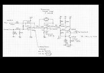
The 10R is the cathode resistor (power tube) to Gnd for ref?
Vref is a votage set by a pot that sets the tube bias ref (Variable)?
The integrator only adjusts the bias when there is no signal..ie a stable ref from the cathode?
2M2 across the first OPamp..correct?
So the 47uF elec would have to be very low leakage...a film cap would be better (size might be an issue)
1.8v led..voltage clamp?
Can you confirm the Transistor numbers looks like BF620? mpsa92?
Diodes across the integrator<< 1n4148?
LM358<<any special reason? why not individual chips<<is it just space saving?
Last question have you tried it?
It might need some kind of fail safe OP tube shut down..buts thats another issue..
Regards
M. Gregg
Last edited:
Just as a thought..
Audio research did something along these lines with the M100...
Can't remember the circuit..
Its only problem was chip failure...
I guess you could always fuse the cathode..
However the sample and hold is always going to be a problem with leakage over time..
I guess the only real way is to use digital processing..and A/D from the cathode and ref then output a bias voltage..no problem with integrators and it could be timed to set at start up or with push button set..
But its way to much effort for the gain..
Regards
M. Gregg
Last edited:
- Status
- This old topic is closed. If you want to reopen this topic, contact a moderator using the "Report Post" button.
- Home
- Amplifiers
- Tubes / Valves
- push pull bias servo