I have a problem with a DIY guitar amp.
The power amp is a Class A SE single EL84. All voltages are correct according to the datasheet and it sounds pretty decent.
Pdiss = +- 10,5 W, B+=270V, Ia=+-40mA.
BUT I have an annoying 100 Hz hum and I can't seem to get rid of it.
The heaters are fed with AC so I don't think the problem lies there (the heaters are 50 Hz).
I suspect the problem to be in the power supply. It's based around an EZ81. I cannot add more filter capacity, following the EZ81 datasheet. There is not enough space in the chassis for a choke.
I think there is too much ripple on the grid2 voltage supply...
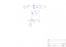
This is the schematic. Does anyone have an idea how to reduce the hum?
Please note this is a guitar amp: It does NOT have to sound HiFi. I will be used with high efficiency speakers (100db/1w) so the hum needs to be very low...
The power amp is a Class A SE single EL84. All voltages are correct according to the datasheet and it sounds pretty decent.
Pdiss = +- 10,5 W, B+=270V, Ia=+-40mA.
BUT I have an annoying 100 Hz hum and I can't seem to get rid of it.
The heaters are fed with AC so I don't think the problem lies there (the heaters are 50 Hz).
I suspect the problem to be in the power supply. It's based around an EZ81. I cannot add more filter capacity, following the EZ81 datasheet. There is not enough space in the chassis for a choke.
I think there is too much ripple on the grid2 voltage supply...
This is the schematic. Does anyone have an idea how to reduce the hum?
Please note this is a guitar amp: It does NOT have to sound HiFi. I will be used with high efficiency speakers (100db/1w) so the hum needs to be very low...
Attachments
If you want very low hum, or no hum in an ideal situation, you really need to rethink the entire PSU. With just 50uF of capacitance, no real filtering of any kind and the inability to add a choke, you're pretty much stuck and left with around 8 volts of ripple.
I know it's a guitar amp, but you could consider regulation for optimal, no hum, performance. You could also loose the Ez81 and replace it with solid state diodes, add a resistor for the voltage drop simulation and add more capacitance.
I know it's a guitar amp, but you could consider regulation for optimal, no hum, performance. You could also loose the Ez81 and replace it with solid state diodes, add a resistor for the voltage drop simulation and add more capacitance.
Last edited:
Member
Joined 2009
Paid Member
Try a capacitor from cathode of the output tube to B+. The idea is to inject some B+ hum into the cathode where it will be amplified by the output valve and appear at the anode. If you get the right amount of injected hum at the anode it will match up with the hum on the B+ rail. Then your output transformer has the same hum on both connections to the primary and hence no hum current will flow through the primary to excite hum in the speaker. You will have to adjust the value of the capacitor from the cathode to B+ and possibly also the cathode resistor bypass capacitor to ensure that together they inject the right amount of hum into the cathode. Roughly speaking the ratio of the cathode bypass cap and the cathode-B+ cap should be close to the gain of the tube (e.g. the cathode-to-B+ cap will be equal to the cathode bypass cap divided by the gain of the tube). Hence, you won't need a large cap between the cathode and B+ to pull off this trick but it does have to be adjusted until it's the right size.
Last edited:
Most sensitive (to PS ripple, which you can measure with your DMM) part of your amplifier would be the driver stage, probably an ECC83. Simply decouple better with an RC stage.... BUT I have an annoying 100 Hz hum and I can't seem to get rid of it... I suspect the problem to be in the power supply...
I think there is too much ripple on the grid2 voltage supply... Does anyone have an idea how to reduce the hum?
Your EL84 might have an isolation problem (too low resistance from heater to cathode) which you can check by feeding DC to the heaters. Did you ground your heaters btw?
Next could be a grounding issue; larger signal (or PS) currents interacting with small signal currents because of faulty routing.
Finally you could suffer from direct radiation of power tranny in to output tranny. Try rotating the latter and measure or listen for differences.
At first you can see if the voltage amplifying stage has any role of the hum by removing this tube (12AX7 ?).
If the hum stays while this tube is removed, then you can forget it.
You have an OPT with a +Ub link. Is this an old style tube radio OPT or ordinary PP OPT or what ?
Have you tried to supply +Ub at the end of the primary instead of this tap ?
If the hum stays while this tube is removed, then you can forget it.
You have an OPT with a +Ub link. Is this an old style tube radio OPT or ordinary PP OPT or what ?
Have you tried to supply +Ub at the end of the primary instead of this tap ?
I agree with artosalo, need more information about output transformer, on old tube radios output transformers with a primary coil used as filter were common...it was used after the rectifier as inductance for LC filtering. If so i would re-arrange connections as in the old radios schemes.
Also do artosalo test, remove preamp tubes or if you have master volume directly before EL84 put this at 0 , if still hum problem is around ouput stage.
Also try removing EL84 to be sure you're not having magnetic coupling between PT and OT.
Also do artosalo test, remove preamp tubes or if you have master volume directly before EL84 put this at 0 , if still hum problem is around ouput stage.
Also try removing EL84 to be sure you're not having magnetic coupling between PT and OT.
Wow guys, incredible response! Thanks for all the thoughts
i will try this if everything else fails, but the EZ81 has a significant effect on the sound, which is considered 'nice' when using the amp for guitar. So I would like to keep the EZ81 if possible.
The grounding is of the 'Star ground' type. I don't think the problem lies there, but I will check it")
The power transformer is quite far away from the output tranny. If I'm correct, interaction between those two would create a 50 Hz hum and my problem is 100Hz (rectifier hum...)
You are spot on with the tube radio OT. I took all the transformers from an old RFT radio.
It has indeed an extra winding.
There is a large, primary wiring to be used just like in every single ended output transformer. Then, there is small (primary) winding, in anti-phase with the large primary winding, through which the grid 2 current and the entire preamp current are fed.
Because they are in anti-phase, a part of the power supply ripple is magnetically canceled.
Also, it is some kind of L-filter reducing AC on the preamp and grid2 supplies.
This has been told to me by an experienced tube amp builder.
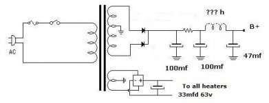
He also told me to copy (more or less) the output stage from the old radio. I added it as an attachement. Biggest difference is the grid 2 setup (my grid 2 voltage is also quite a bit higher... )Of course, the entire radio preamp and tuner was fed through that little 'anti-phase' primary winding. In my guitar amp, only one 12AX7 and grid 2 are fed throught the winding...
I will try changing the connections of my OT. Maybe it helps
I know it's a guitar amp, but you could consider regulation for optimal, no hum, performance. You could also loose the Ez81 and replace it with solid state diodes, add a resistor for the voltage drop simulation and add more capacitance.
i will try this if everything else fails, but the EZ81 has a significant effect on the sound, which is considered 'nice' when using the amp for guitar. So I would like to keep the EZ81 if possible.
This sounds like an interesting idea. If I have the right cap lying around, I'm gonna try it. Thanks!Try a capacitor from cathode of the output tube to B+.
Heaters are referenced to cathode voltage voltage using 2 100Ohm resistors.Your EL84 might have an isolation problem (too low resistance from heater to cathode) which you can check by feeding DC to the heaters. Did you ground your heaters btw?
Next could be a grounding issue; larger signal (or PS) currents interacting with small signal currents because of faulty routing.
Finally you could suffer from direct radiation of power tranny in to output tranny. Try rotating the latter and measure or listen for differences.
The grounding is of the 'Star ground' type. I don't think the problem lies there, but I will check it
The power transformer is quite far away from the output tranny. If I'm correct, interaction between those two would create a 50 Hz hum and my problem is 100Hz (rectifier hum...)
At first you can see if the voltage amplifying stage has any role of the hum by removing this tube (12AX7 ?).
You have an OPT with a +Ub link. Is this an old style tube radio OPT
Have you tried to supply +Ub at the end of the primary instead of this tap ?
Without the preamp tubes it has the same problem, the problem is definitely in the EL84 stage.I agree with artosalo, need more information about output transformer, on old tube radios output transformers with a primary coil used as filter were common...it was used after the rectifier as inductance for LC filtering. If so i would re-arrange connections as in the old radios schemes.
You are spot on with the tube radio OT. I took all the transformers from an old RFT radio.
It has indeed an extra winding.
There is a large, primary wiring to be used just like in every single ended output transformer. Then, there is small (primary) winding, in anti-phase with the large primary winding, through which the grid 2 current and the entire preamp current are fed.
Because they are in anti-phase, a part of the power supply ripple is magnetically canceled.
Also, it is some kind of L-filter reducing AC on the preamp and grid2 supplies.
This has been told to me by an experienced tube amp builder.
He also told me to copy (more or less) the output stage from the old radio. I added it as an attachement. Biggest difference is the grid 2 setup (my grid 2 voltage is also quite a bit higher... )Of course, the entire radio preamp and tuner was fed through that little 'anti-phase' primary winding. In my guitar amp, only one 12AX7 and grid 2 are fed throught the winding...
I will try changing the connections of my OT. Maybe it helps
Attachments
Hi guys! I found the problem, and kinda solved it, but I don't know why...
I was playing with the OT primary taps.
When I disconnected the mid tap (B+ tap on the schematic) and i connected B+ right before the g2 resistor (so on the end of the 'small' OT tap), it worked great! Not the slightest hum audible, very good!
But why?
I played a little further: I put B+ back where it was before, but 'shorted' the small OT tap.
... No hum, but very stranged things happened: grid2 started SUCKING current like a bastard (20mA!!), and the anode voltage dropped to ... 0V... So a 280V voltage drop accross the output transformer... I immediately shut it off, this couldn't be healthy. I did not try if it worked or not (probably not).
I think this means the output transformer is not wired the way I think it is... But how can this explain this strange behaviour?...
because you connected the OT wrong. B+ goes on one end of the OT and the other end goes to the anode of the valve in this case el84.Also you should add a choke in the filter line or a resistor.
No, just one of the connections had come loose.

Also, note that this is a OT with a primary with 3 taps, one of which is a 'choke' winding...
But right now it's clear to me that the OT connections aren't as I was thinking they are. My measurements aren't really helping me out. Except that when I lose the choke winding (short it, or leave it open), the hum is gone which is at least a bit strange.
anyway, i assume you solved the problem with the hum?
Yes, I solved it. Thanks for the help!
The problem was that I didn't copy the 1k resistor between the OT 'choke' tap and the 50 µF cap from the old radio schematic.
The cap load current flowing through the choke winding (the OT) caused the hum.
Now, there's almost no hum left
- Status
- This old topic is closed. If you want to reopen this topic, contact a moderator using the "Report Post" button.
- Home
- Amplifiers
- Tubes / Valves
- SE EL84 amp - reducing 100Hz hum